Conquer Chaos: Machine Vision Cable Routing Best Practices for Flawle...
In machine vision systems, your cables are the critical lifelines transmitting data, power, and control signals. Poor routing isn’t just messy; it’s a prime culprit behind signal degradation, electromagnetic interference (EMI), physical damage, and costly system downtime. Mastering cable routing best practices is essential for achieving reliable inspections, maximizing throughput, and protecting your investment.
Here’s your comprehensive guide to routing machine vision cables like a pro:
1. Choose the Right Cable for the Job
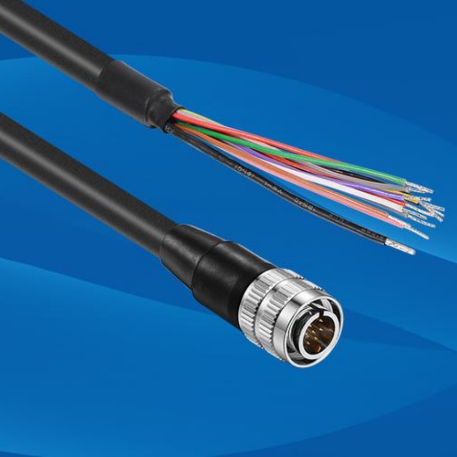
- Quality Matters: Invest in high-quality, shielded cables designed specifically for industrial use. Look for robust jacketing (e.g., PUR/PVC) resistant to oils, chemicals, and abrasion.
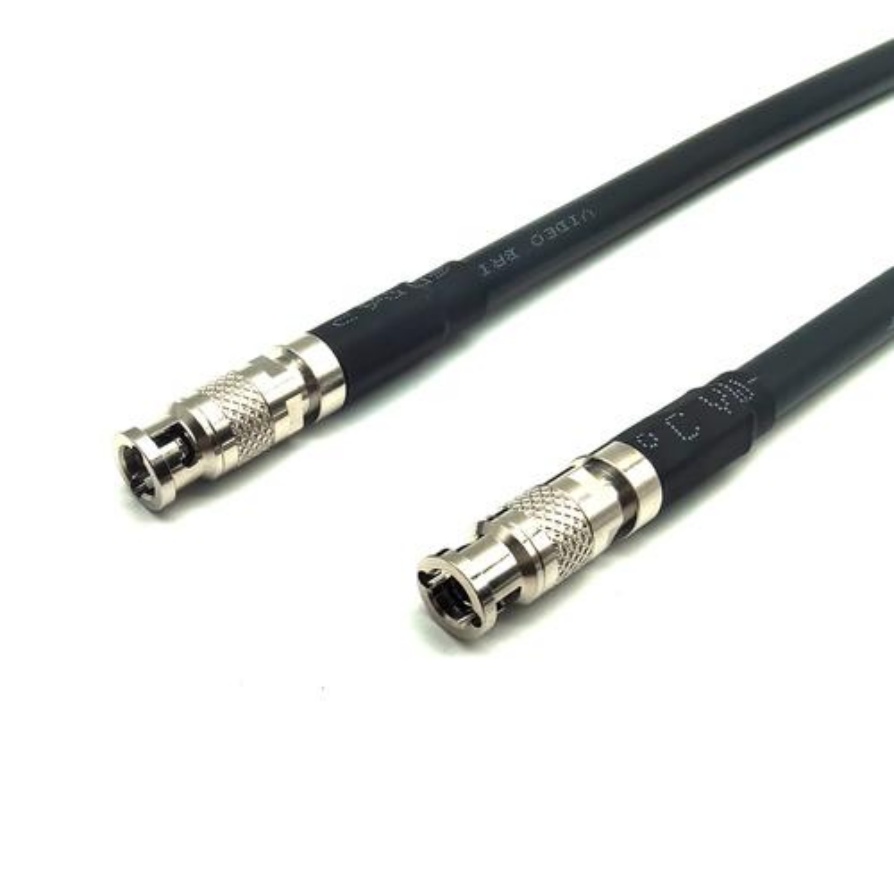
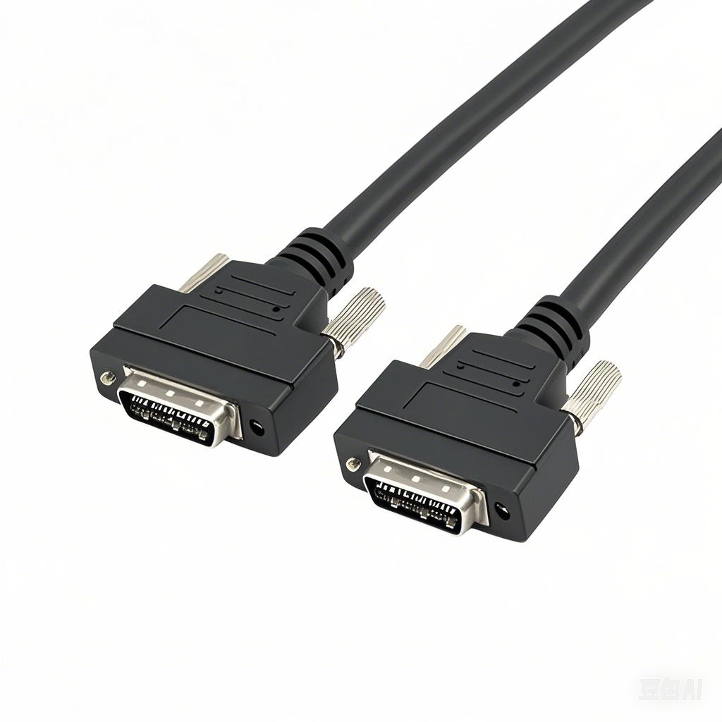
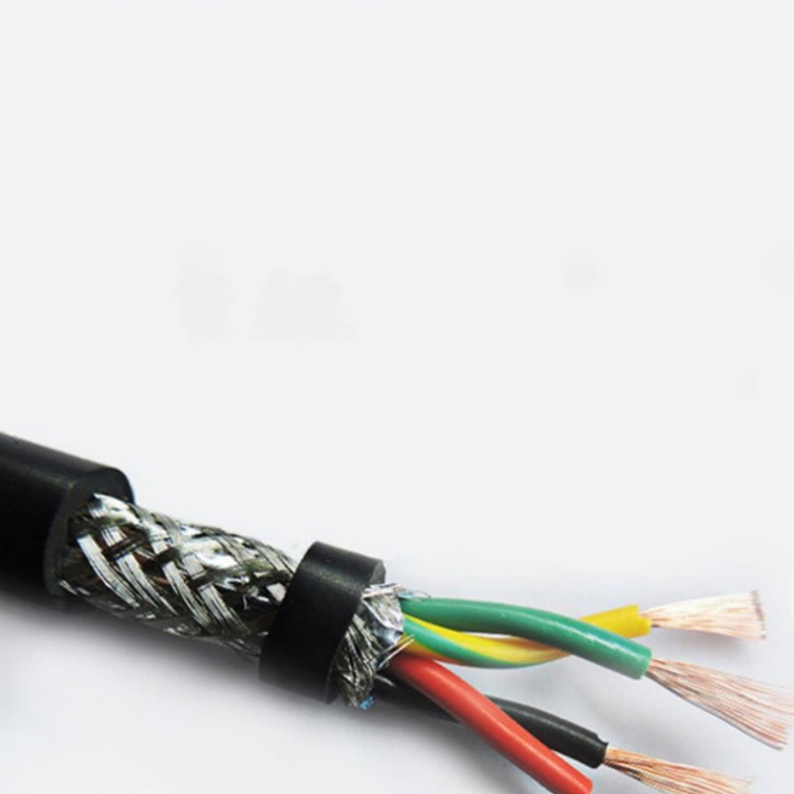
- Shielding is Non-Negotiable: Use double-shielded (foil + braid) cables for critical signals (especially Camera Link, CoaXPress, GigE Vision). This minimizes EMI/RFI pickup and radiation.
- PoE Considerations: For Power over Ethernet (PoE) cameras, ensure cables meet the required category rating (e.g., Cat 6a for higher power) and are properly terminated.
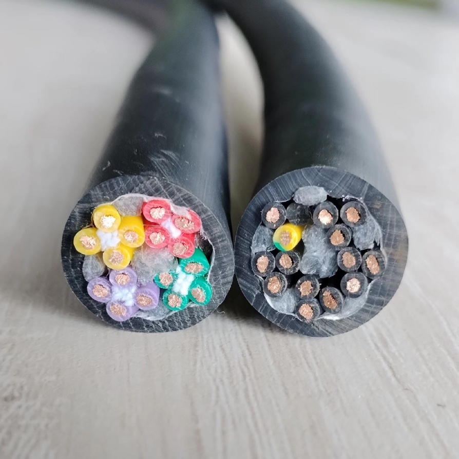
- Flexing Needs: Cables routed to moving parts (e.g., robot arms, gantries) MUST be rated for continuous flexing. Use dedicated flex-rated cables with specialized conductors and strain relief.
2. Strategic Pathway Planning
- Dedicated Cable Runs: Avoid routing vision cables in the same conduits, trays, or sleeves as high-power cables (AC motors, VFDs, welding equipment, heaters).
- Maintain Physical Separation: Keep minimum distances from EMI sources:
- At least 12 inches (30 cm) from AC power lines.
- More than 24 inches (60 cm) from VFDs, large motors, or welding cables. If close proximity is unavoidable, cross power cables at 90-degree angles to minimize inductive coupling.
- Utilize Protective Pathways: Route cables through:
- Cable carriers (Energy Chains): Essential for organized routing on moving axes. Ensure correct fill ratio and strain relief at entry/exit points.
- Conduits and Cable Trays: Offer physical protection. Use separate compartments within trays for vision vs. power cables. Ground metal conduits/trays properly.
- Flexible Conduit (Loom) or Spiral Wrap: Good for stationary runs or shorter moving segments needing abrasion resistance.
3. Minimizing Electromagnetic Interference (EMI)
- Separation is Key: As above, distance from noise sources is your primary defense.
- Proper Grounding (Earthing):
- Shield Termination: Terminate cable shields correctly and consistently at both ends (typically chassis ground) for optimal noise rejection. Use appropriate EMI connectors and ensure grounding points are clean and secure. Avoid “pigtail” shield connections.
- Ground Loops: Prevent ground loops by ensuring all system components (cameras, controllers, PLCs) share a single-point, high-quality earth ground connection.
- Filtering: Use ferrite cores (clamp-on or toroidal) near connection points if interference issues persist despite other measures.
4. Preventing Physical Damage
- Avoid Sharp Bends: Respect the cable’s minimum bend radius (usually 6-10x the cable diameter). Sharp bends stress conductors and can break shields.
- Protect from Moving Parts: Route cables away from pinch points, shearing edges, gears, or chain drives. Inside cable carriers offers the best protection.
- Strain Relief: Always use proper strain relief at cable entry/exit points from connectors, junction boxes, controllers, and carriers. Avoid tension on the connector itself.
- Avoid Environmental Hazards: Keep cables away from excessive heat sources, direct UV exposure (unless UV-rated), chemicals, or potential crushing points (e.g., underfoot, under machinery).
5. Labeling and Documentation
- Clear Identification: Label both ends of every cable clearly using tags or markers. Include purpose (e.g., “Basler Cam 1 – Trigger,” “Cognex IS7402 PoE”).
- Maintain Schematics: Keep up-to-date connection diagrams and routing layouts for future troubleshooting, maintenance, or upgrades.
- Cable Management Accessories: Utilize cable ties (use with care – avoid over-tightening), clamps, mounts, and Velcro straps to keep bundles organized. Consider sleeving for grouping and protection. Hook-and-loop straps are excellent for areas needing adjustment.
6. Connection Points & Inspection
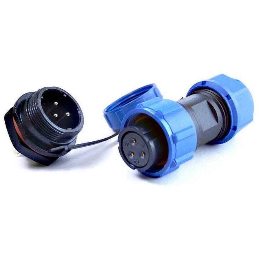
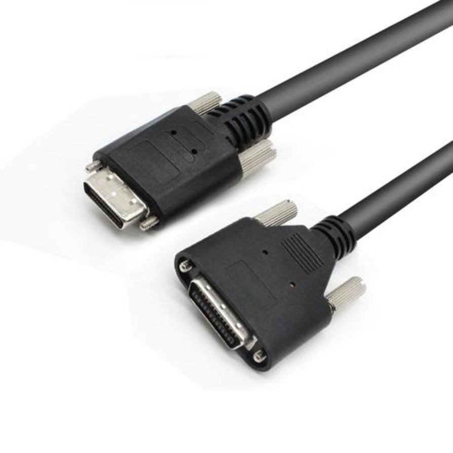
- Secure Connections: Ensure connectors are fully seated and locked (e.g., screws for D-Sub/Camera Link, latches for MDR). Loose connections cause intermittent faults.
- Drip Loops: Add a small drip loop (U-shaped sag) near connection points to prevent tension and pull liquids away from connectors.
- Regular Inspections: Periodically check cables for:
- Signs of wear, abrasion, or crushing.
- Damaged connectors or bent pins.
- Loose shield connections or strain relief.
- Fraying near flex points.
Conclusion: Protect Your Vision Investment
Flawless machine vision performance hinges on pristine signal integrity and robust reliability. By implementing these cable routing best practices – prioritizing quality cables, strategic separation, proper grounding, physical protection, meticulous organization, and diligent maintenance – you dramatically reduce the risks of interference, damage, and failure. The upfront effort pays off significantly in reduced troubleshooting headaches, maximized system uptime, consistent inspection accuracy, and a longer lifespan for your critical vision components.
Invest wisely in your cables and their routing – it’s the essential infrastructure your vision system depends on for success.


