How to Document Machine Vision Cable Installations: A Practical Guide
Ensuring reliable machine vision system performance often hinges on seemingly mundane details – like cable management. Properly documenting your machine vision cable installations isn’t just neatness; it’s critical for efficient troubleshooting, maintenance, upgrades, and compliance. Here’s a practical, step-by-step guide to get it done right.
Why Proper Cable Documentation is Non-Negotiable
- Faster Troubleshooting: When a camera goes offline or a cable fails, hours are wasted tracing lines without clear documentation. Labeled cables and clear diagrams pinpoint issues instantly.
- Smoother Maintenance & Upgrades: Swapping a camera, adding a device, or rerouting cables becomes straightforward when you know exactly where every cable runs and connects.
- Onboarding & Knowledge Transfer: New engineers or technicians can understand the system layout quickly without relying solely on tribal knowledge.
- Audits & Compliance: Many industries require documentation for electrical safety and quality management standards (ISO, GMP, etc.).
- Reduced Downtime: Minimizing guesswork during repairs translates directly to less production loss.
Essential Elements of Effective Cable Documentation
- Comprehensive Cable Labels (On EVERY Cable):
- Location: Where does it start (e.g.,
Cabinet-A, PLC-Rack) and where does it terminate (e.g., Sensor-Lane3, Camera-Station4_Trigger)? Be specific.
- Cable Identifier: A unique ID for tracking (e.g.,
MV-CAM-001, MV-PWR-012). Use a consistent naming scheme.
- Signal Type (Optional but Recommended): Indicate power (
PWR), data (e.g., GigE, Camera Link, CoaXPress), digital I/O (DIO, Trigger), or specific protocols (e.g., RS232, EtherNet/IP).
- Detailed Connection Diagrams & Schematics:
- Physical Layout: A diagram (like a block diagram or simple CAD sketch) showing the relative positions of cabinets, machines, cameras, lights, sensors, etc., and the cables connecting them.
- Connectivity Map: A logical diagram showing what connects to what at the device level (e.g., Camera A Port 1 -> Frame Grabber Port 3; Light Controller Output 2 -> Ring Light Input). Include the cable IDs.
- Termination Details: Clearly label pinouts (e.g.,
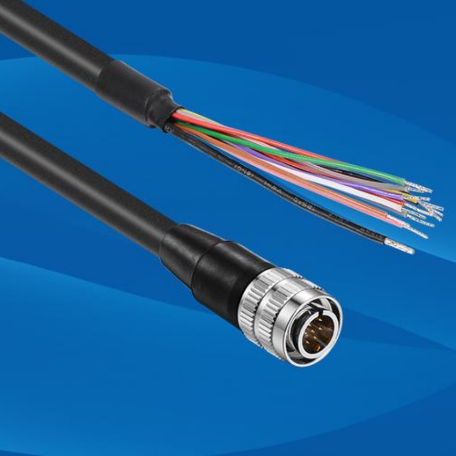
Pin 1: +24V, Pin 2: GND, Pin 3: Trigger In) at both ends for custom cables or critical connections. Reference connector types (e.g., M8, M12, RJ45). Photos can supplement this.
- Cable Run Photos & Notes:
- Photos: Take clear pictures during installation:
- Cable entry/exit points from panels, control cabinets, and machines.
- Cable routing paths, especially through cable trays, conduits, or across machine frames.
- Junction boxes or patch panels.
- Cable bundling points and strain relief installations.
- Close-ups of termination points.
- Notes: Briefly describe the route in text (e.g., “From Cabinet C to Camera 5: Enters rear conduit, runs along overhead tray T2 for 3m, exits tray above machine, drops down cable carrier Arm1 to Camera mount”).
- Cable Specifications & Lists:
- Master Cable List: A spreadsheet (or equivalent) serving as an index.
- Key Fields:
- Cable ID
- Description (e.g., “GigE Camera Cable”, “24VDC Power to Dome Light”)
- Signal Type (Voltage/Protocol)
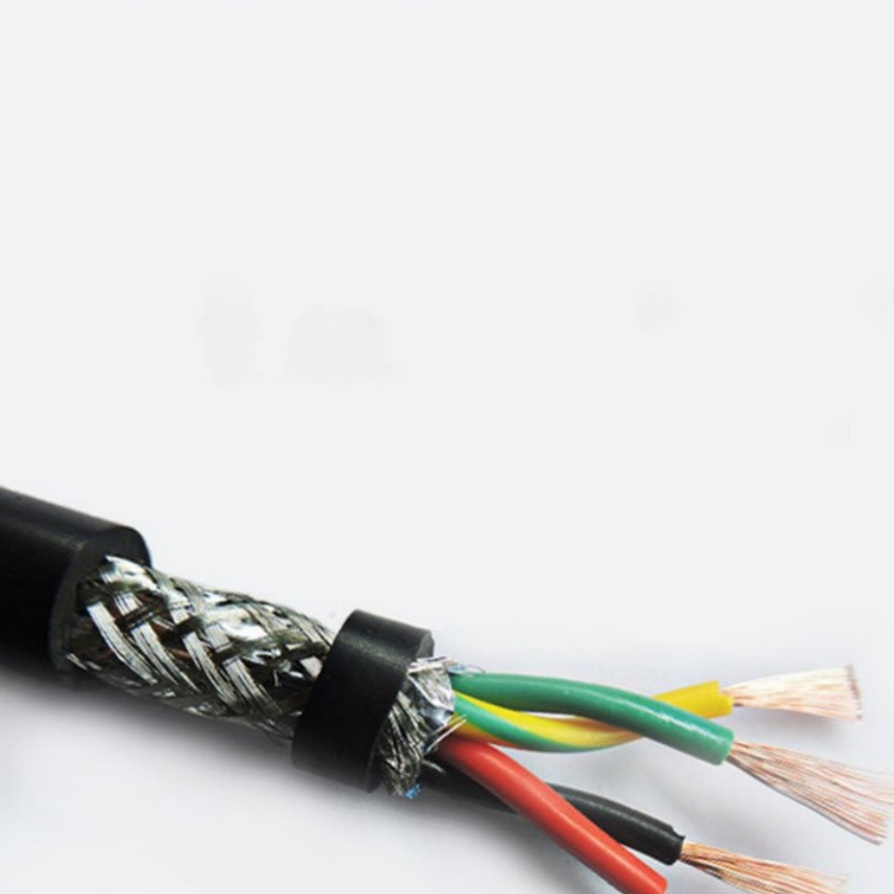
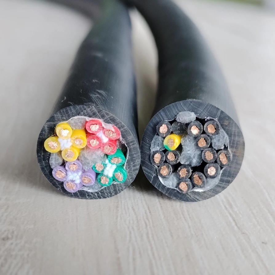
- Cable Type & Shielding (e.g., Cat6a S/FTP, PUR shielded power cable)
- Conductor Gauge (for power cables)
- Length
- Source Device/Location & Port
- Destination Device/Location & Port
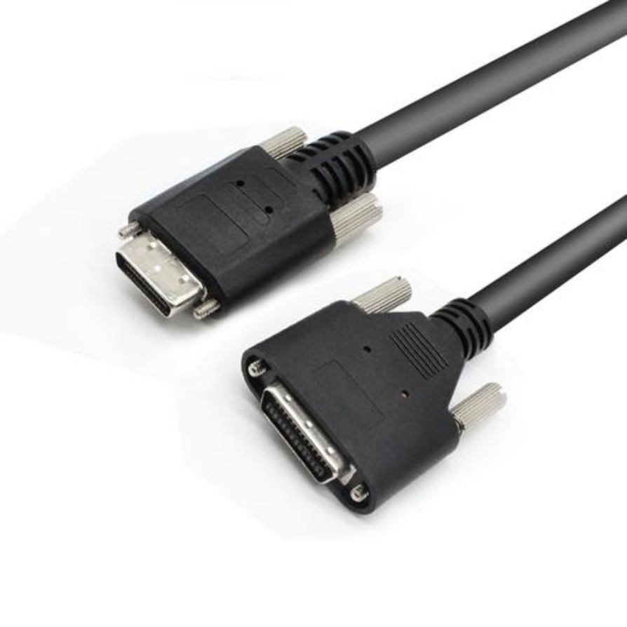
- Connector Type A
- Connector Type B
- Installation Date
- Photos/Document References
Step-by-Step Documentation Process
- Plan Before Installation: Decide your naming convention, labeling method, and documentation standards before pulling the first cable. Gather labeling tools and documentation templates.
- Label Both Ends First: As you prepare each cable, label both ends clearly and durably before installation. Use high-quality, industrial-grade labels (e.g., heat-shrink labels, self-laminating vinyl tags) resistant to chemicals, oil, and abrasion.
- Photograph As You Go: Take photos at key stages: before running, during routing, during termination, and after completion. Capture context (adjacent cables, landmarks).
- Update Diagrams & Lists Continuously: Don’t wait until the end. Update your diagrams and master cable list immediately after installing each cable or group of cables. Note deviations from the plan.
- Capture Termination Details: Document pinouts and connector types directly on schematics or in termination tables as connections are made. Take close-up photos.
- Record Cable Routes: Make clear notes or sketch simple maps showing cable paths. Mark photos with directional arrows.
- Finalize Master List: After installation, compile all information into your centralized master cable list, ensuring every cable ID has corresponding entries in diagrams and photos.
- Store Accessibly: Keep documentation in a well-known, secure location accessible to relevant personnel (e.g., network drive, cloud storage like SharePoint or Google Drive, physical binder stored near equipment). Back it up! Version control helps track changes.
Choosing and Applying Labels: Best Practices
- Choose Industrial Labels: Standard office labels will fail in industrial environments. Heat-shrink labels offer excellent durability. Self-laminating vinyl tags with clear protective tops work well for tie-on tags.
- Legibility: Use a clear, bold font. Ensure labels are large enough to read easily. Thermal transfer printers often produce the most durable and clear results.
- Placement: Affix labels close to the connector (within 6-12 inches) on both ends, ensuring they are visible without excessive cable manipulation.
- Durability: Labels must withstand vibration, dust, oils, coolants, and temperature variations typical of manufacturing settings. Test label samples beforehand.
- Consistency: Place labels at consistent distances from connectors throughout the installation.
Critical Tools for the Job
- Industrial label printer (e.g., Brady, Panduit, Dymo Rhino)
- High-quality industrial labels (heat-shrink, vinyl self-laminating, nylon cable flags)
- Heat gun (for heat-shrink labels)
- Cable ties (for securing labels/tags)
- Permanent markers (UV-resistant, industrial)
- Camera (Smartphone often sufficient with good lighting)
- Documentation templates (Spreadsheet for list, drawing tools for schematics)
- Accessible storage solution (Cloud drive, local server)
Maintaining Your Documentation
Documentation is useless if it’s outdated.
- Update Immediately: When adding, removing, or changing any cable or connection, immediately update the master list, diagrams, photos, and labels. Over-labeling is better than under-labeling.
- Regular Reviews: Schedule periodic checks (e.g., quarterly) to verify physical installations match the documentation. Note any discrepancies.
- Version Control: Use a version number and date on all master documents. Archive old versions when major updates occur.
Conclusion
Investing time in meticulously documenting your machine vision cable installations pays enormous dividends in operational efficiency, troubleshooting speed, and long-term system integrity. By using clear labels, detailed diagrams, comprehensive lists, supporting photos, and consistent practices, you create invaluable system knowledge that empowers your team and minimizes costly downtime. Treat cable documentation with the same importance as the hardware itself – it’s foundational to a robust, maintainable vision system. Don’t wait for a crisis to start; implement these practices on your next installation or as part of your next maintenance window.


