How to Calculate the Power Loss in Machine Cable
Machine cables are critical for transmitting electrical energy to industrial equipment (e.g., motors, pumps, and conveyors). However, unavoidable power loss occurs during transmission, primarily due to the cable’s inherent resistance. Excessive power loss wastes energy, raises cable temperatures (risking insulation damage), and reduces equipment efficiency. This guide explains the core principles, step-by-step calculation method, and practical considerations to accurately quantify power loss in machine cables.
1. Key Factors Affecting Power Loss in Machine Cables
Power loss in cables stems from Joule heating (I²R loss), where electrical energy converts to heat as current flows through a resistive conductor. The three primary factors determining this loss are:
- Cable Resistance (R): Dependent on the cable’s material (copper vs. aluminum), cross-sectional area (A), length (L), and operating temperature (T). Copper has lower resistance than aluminum (e.g., 0.0172 Ω·mm²/m for copper vs. 0.0283 Ω·mm²/m for aluminum at 20°C).
- Operating Current (I): The actual root-mean-square (RMS) current flowing through the cable during equipment operation (not just the cable’s rated current). This may need measurement (e.g., with a clamp meter) if the load varies.
- Current Type: Single-phase vs. three-phase systems—three-phase cables require adjusting for balanced or unbalanced current distribution.
2. Step-by-Step Calculation Method
The core formula for power loss (Pₗₒₛₛ) in a single conductor is:
Pₗₒₛₛ = I² × R
(Units: Watts, W; I in Amperes, A; R in Ohms, Ω)
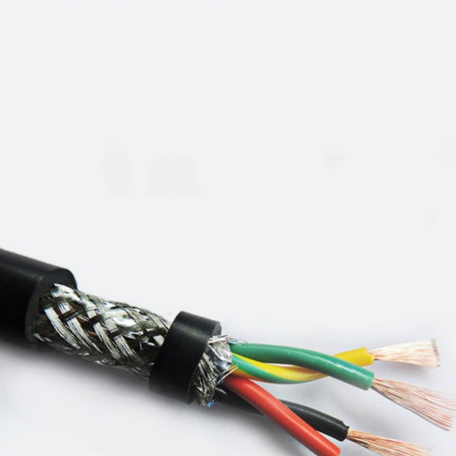
For multi-conductor cables (e.g., 3-core cables for three-phase motors), calculate loss per conductor and sum the total. Below is a detailed workflow:
Step 1: Gather Cable Specifications
Retrieve key parameters from the cable’s datasheet or physical inspection:
- Conductor material: Confirm if it’s copper (Cu) or aluminum (Al).
- Cross-sectional area (A): Typically listed in mm² (e.g., 6 mm², 10 mm²) or AWG (convert AWG to mm² using standard tables if needed).
- Cable length (L): Measure the actual length of the cable between the power source and the machine (in meters, m). Avoid estimating—use a tape measure for accuracy.
- Temperature coefficient (α): For copper, α = 0.00393 °C⁻¹ (at 20°C); for aluminum, α = 0.00403 °C⁻¹. This corrects resistance for temperature changes.
Step 2: Calculate the Cable’s DC Resistance (Rₜ) at Operating Temperature
Cable resistance increases with temperature. First, calculate the reference resistance (R₂₀) at 20°C (standard for datasheets), then adjust to the actual operating temperature (Tₒₚ).
Formula for R₂₀ (20°C reference resistance):
R₂₀ = (ρ × L) / A
Where:
- ρ (resistivity) = 0.0172 Ω·mm²/m (copper) or 0.0283 Ω·mm²/m (aluminum) at 20°C.
Formula for Rₜ (resistance at operating temperature Tₒₚ):
Rₜ = R₂₀ × [1 + α × (Tₒₚ – 20)]
- Tₒₚ: Actual operating temperature of the cable (°C). Measure with a thermal imager or use the equipment’s ambient temperature + estimated temperature rise (e.g., 30°C for lightly loaded cables, 50°C for heavily loaded cables).
Example: A 10 m copper cable (A = 6 mm²) operating at 40°C:
R₂₀ = (0.0172 × 10) / 6 ≈ 0.0287 Ω
Rₜ = 0.0287 × [1 + 0.00393 × (40 – 20)] ≈ 0.0287 × 1.0786 ≈ 0.0310 Ω
Step 3: Determine the Operating Current (I)
The actual current flowing through the cable depends on the machine’s load. Use one of these methods:
- Direct measurement: Use a clamp meter to measure RMS current at the cable (ensure the meter is rated for AC/DC, matching the system).
- Equipment nameplate: For constant-load machines (e.g., a 5 kW motor), calculate current using P = V × I × PF (single-phase) or P = √3 × V × I × PF (three-phase), where PF = power factor (typically 0.7–0.9 for inductive loads).
Example: A 5 kW, 230 V single-phase motor with PF = 0.8:
I = P / (V × PF) = 5000 / (230 × 0.8) ≈ 27.17 A
Step 4: Calculate Total Power Loss
Case 1: Single-Phase Systems (e.g., 2-core cables: live + neutral)
Power loss occurs in both conductors. Total loss (Pₜₒₜₐₗ) is:
Pₜₒₜₐₗ = 2 × I² × Rₜ
Example: Using the 10 m copper cable (Rₜ = 0.0310 Ω) and I = 27.17 A:
Pₜₒₜₐₗ = 2 × (27.17)² × 0.0310 ≈ 2 × 738.21 × 0.0310 ≈ 45.77 W
Case 2: Three-Phase Systems (e.g., 3-core cables: L1, L2, L3)
For balanced three-phase loads (equal current in each conductor), total loss is:
Pₜₒₜₐₗ = 3 × I² × Rₜ
Example: A 15 kW, 400 V three-phase motor (PF = 0.85) with a 15 m aluminum cable (A = 10 mm², Tₒₚ = 45°C):
- Calculate I: I = P / (√3 × V × PF) = 15000 / (1.732 × 400 × 0.85) ≈ 15000 / 598.88 ≈ 25.05 A
- Calculate R₂₀: R₂₀ = (0.0283 × 15) / 10 ≈ 0.0425 Ω
- Calculate Rₜ: Rₜ = 0.0425 × [1 + 0.00403 × (45 – 20)] ≈ 0.0425 × 1.1008 ≈ 0.0468 Ω
- Total loss: Pₜₒₜₐₗ = 3 × (25.05)² × 0.0468 ≈ 3 × 627.50 × 0.0468 ≈ 87.8 W
3. Common Pitfalls to Avoid
- Using rated current instead of actual current: Cables often operate below rated current (e.g., a 30 A-rated cable powering a 25 A motor). Using rated current overestimates loss.
- Ignoring temperature correction: At 60°C, copper cable resistance increases by ~15% vs. 20°C—omitting this correction underestimates loss.
- Neglecting neutral conductors in single-phase systems: Power loss occurs in both live and neutral wires; calculating only one conductor halves the actual loss.
4. Practical Applications
Accurate power loss calculations help:
- Select appropriately sized cables (e.g., upgrading from 6 mm² to 10 mm² copper cable reduces resistance and loss).
- Estimate energy waste (e.g., 50 W loss over 8,760 hours/year = 438 kWh wasted, costing ~\(52 at \)0.12/kWh).
- Prevent overheating (e.g., a 100 W loss in a confined cable may raise temperature beyond insulation limits).
Conclusion
Calculating power loss in machine cables relies on understanding Joule heating principles and accurately measuring/calculating resistance and current. By following the step-by-step method—from gathering cable specs to correcting for temperature and summing multi-conductor losses—engineers and technicians can optimize cable selection, reduce energy waste, and ensure safe equipment operation.


