5 Steps to Select the Perfect Machine Vision Cable for Your Setup
Step 1: Identify Your Signal Type and Bandwidth Requirements
Machine vision systems use various communication protocols, each with unique cable requirements:
GigE Vision:
Bandwidth: Up to 10 Gbps (Cat 6a/Cat 7 cables).
Cable Type: Shielded twisted-pair (STP) Ethernet cables with RJ45 connectors.
Camera Link:
Bandwidth: 2.04–6.8 Gbps.
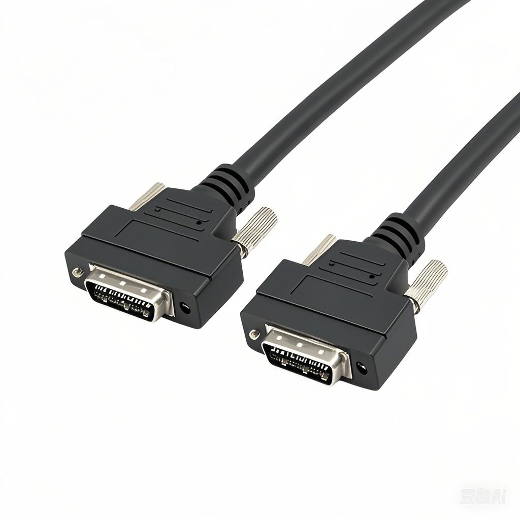
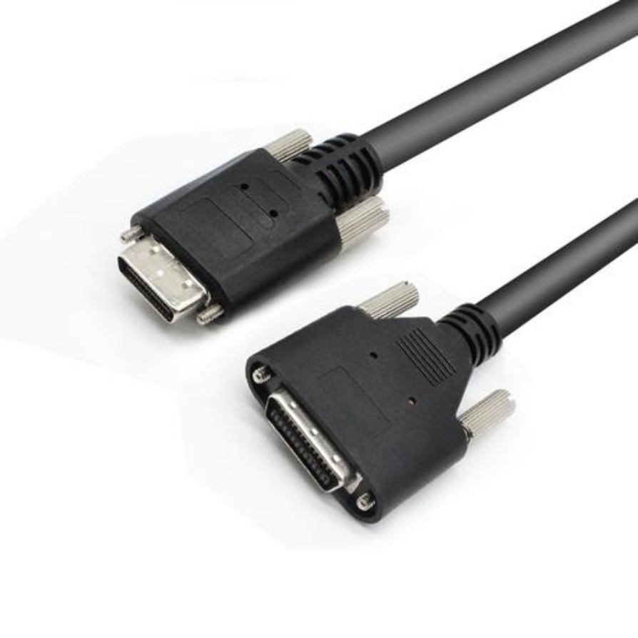
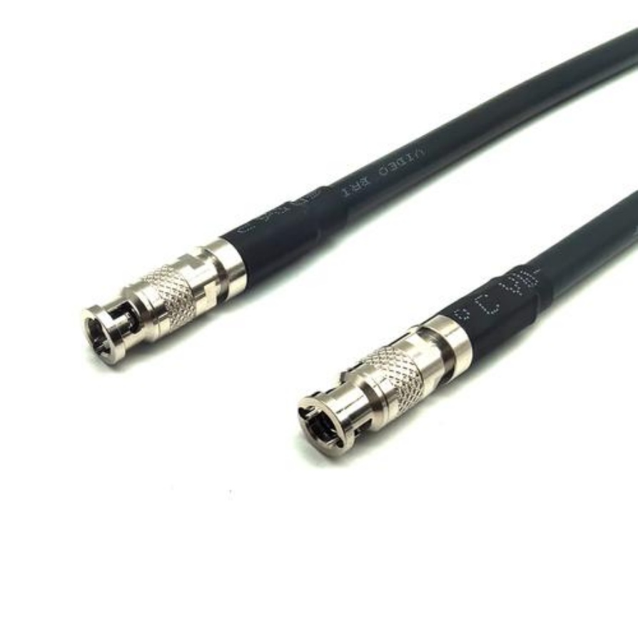
Cable Type: Multi-coaxial cables with MDR-26 or HDBNC connectors.
CoaXPress (CXP):
Bandwidth: 6.25–50 Gbps.
Cable Type: High-flex coaxial cables with 75 Ω impedance.
USB3 Vision:
Bandwidth: 5 Gbps.
Cable Type: Shielded USB 3.0/3.1 cables with locking connectors.
Action: Match the cable’s rated bandwidth to your camera’s resolution and frame rate. For example, a 25-megapixel camera at 60 fps requires ≥10 Gbps bandwidth.
Step 2: Evaluate Environmental and Mechanical Stressors
Machine vision cables often operate in harsh industrial environments. Consider these factors:
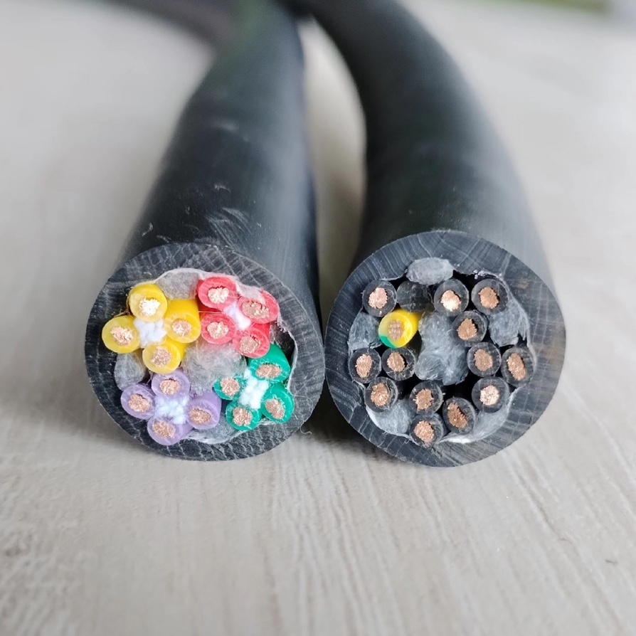
A. Flexibility and Bend Radius
Static Installations: Standard cables with a bend radius ≥10× diameter.
Robotic Arms/Cable Carriers: High-flex cables with ≤5× bend radius (e.g., Igus Chainflex).
B. Temperature and Chemicals
High Temperatures: Silicone or PUR jackets withstand -40°C to +150°C.
Oil/Chemical Exposure: TPE or FEP jackets resist degradation.
C. EMI/RFI Interference
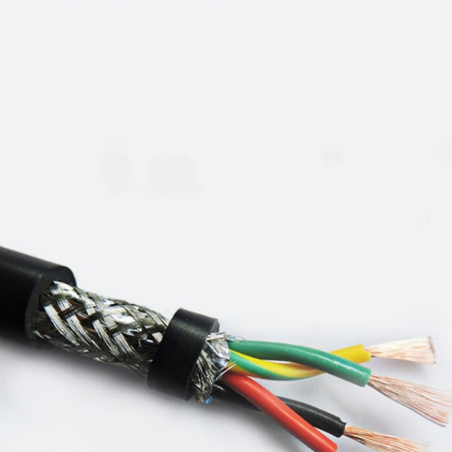
Noisy Environments: Double-shielded (foil + braid) cables with >90 dB shielding effectiveness.
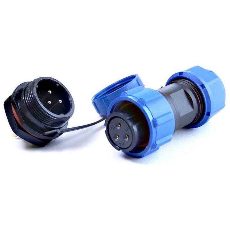
Case Study: A food packaging line with frequent washdowns used PUR-jacketed GigE cables with IP69K-rated connectors to resist moisture and cleaning agents.
Step 3: Determine Cable Length and Signal Integrity
Signal attenuation and latency increase with cable length, especially for high-speed protocols:
Protocol Max Reliable Length (Uncompressed)
GigE Vision 100 meters (Cat 6a)
Camera Link 10 meters
CoaXPress 40 meters (CXP-6)
USB3 Vision 5 meters
Solutions for Long Distances:
Fiber Optic Converters: Extend GigE Vision to 2 km with single-mode fiber.
Signal Repeaters: Boost Camera Link signals every 10 meters.
Rule of Thumb: Keep cables as short as possible. For 10+ meters, prioritize low-attenuation cables (e.g., 22 AWG conductors).
Step 4: Select Connectors and Strain Relief
Connectors are the weakest link in machine vision systems. Key considerations:
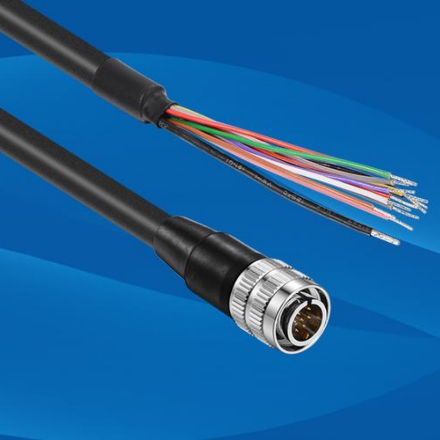
Locking Mechanisms: Screw-lock (M12), push-pull (MDR), or bayonet-style (BNC) to prevent disconnections.
Durability: Gold-plated contacts resist corrosion and ensure stable connections.
Strain Relief: Overmolded connectors or cable clamps reduce stress at termination points.
Pro Tip: For robotic arms, use angled connectors (e.g., right-angle M12) to minimize bending stress.
Step 5: Validate Compatibility and Test in Real Conditions
Even well-specified cables can fail due to unforeseen interactions. Conduct these tests:
Impedance Matching: Use a TDR (Time-Domain Reflectometer) to verify impedance consistency (e.g., 75 Ω for CoaXPress).
Signal Integrity: Test with a high-speed oscilloscope to check for jitter, noise, or eye diagram closure.
Flex Life Test: For dynamic applications, simulate 1 million bend cycles (IEC 61076-2-101 standard).
EMI Testing: Validate shielding effectiveness in the presence of variable-frequency drives or welding equipment.
Example: An automotive assembly plant reduced image dropouts by 90% after replacing generic Ethernet cables with shielded, industrial-grade Cat 7 cables.
Bonus: Cost vs. Performance Trade-Offs
Budget Option: Standard PVC-jacketed cables for static, low-interference setups.
Premium Option: Shielded, high-flex cables with gold-plated connectors for dynamic or mission-critical systems.
Cost-Saving Hack: Use breakout cables (e.g., Camera Link to 4x Coax) instead of multiple single-coax lines.


