Which Cable Length Maximizes Machine Vision System Efficiency
Machine vision systems are the backbone of modern automation, enabling tasks like quality inspection, robotic guidance, and precision measurement. However, even the most advanced cameras, sensors, and processors can underperform if paired with improperly sized cables. Cable length plays a pivotal role in balancing signal integrity, latency, flexibility, and cost in these systems.
Why Cable Length Matters in Machine Vision
Machine vision relies on high-speed data transmission between cameras, processors, and controllers. Longer cables introduce challenges like signal attenuation, electromagnetic interference (EMI), and timing delays, while shorter cables may limit system layout flexibility. Striking the right balance is critical for maintaining accuracy, speed, and reliability.
Key Factors Influencing Optimal Cable Length
1. Signal Integrity and Bandwidth
Problem: Longer cables increase resistance and capacitance, degrading high-frequency signals (e.g., CoaXPress, USB3 Vision, or GigE Vision). This leads to data loss, pixel errors, or dropped frames.
Solution:
Use shielded cables with low attenuation ratings (e.g., <3 dB/100m for GigE).
Adhere to maximum length limits per interface standard:
GigE Vision: ≤100 meters (328 ft) with CAT6a.
USB3 Vision: ≤5 meters (16.4 ft) without repeaters.
CoaXPress: ≤40 meters (131 ft) at 6.25 Gbps.
For long-distance setups, deploy fiber optic cables or signal boosters.
2. Latency and Synchronization
Problem: Excessively long cables delay signal transmission, causing misalignment in time-sensitive tasks like high-speed sorting or multi-camera setups.
Solution:
Keep cables as short as possible for real-time applications (e.g., robotic pick-and-place).
Use synchronization protocols like GenICam or IEEE 1588 to coordinate devices.
3. Flexibility and Maintenance
Problem: Overly short cables restrict equipment placement and strain connectors during reconfiguration.
Solution:
Allow slack (10–20% extra length) for adjustments without violating bend radius limits.
Use modular connectors (e.g., M12 or RJ45) for easy replacements.
4. EMI and Noise Susceptibility
Problem: Longer cables act as antennas, picking up interference from motors, inverters, or wireless devices.
Solution:
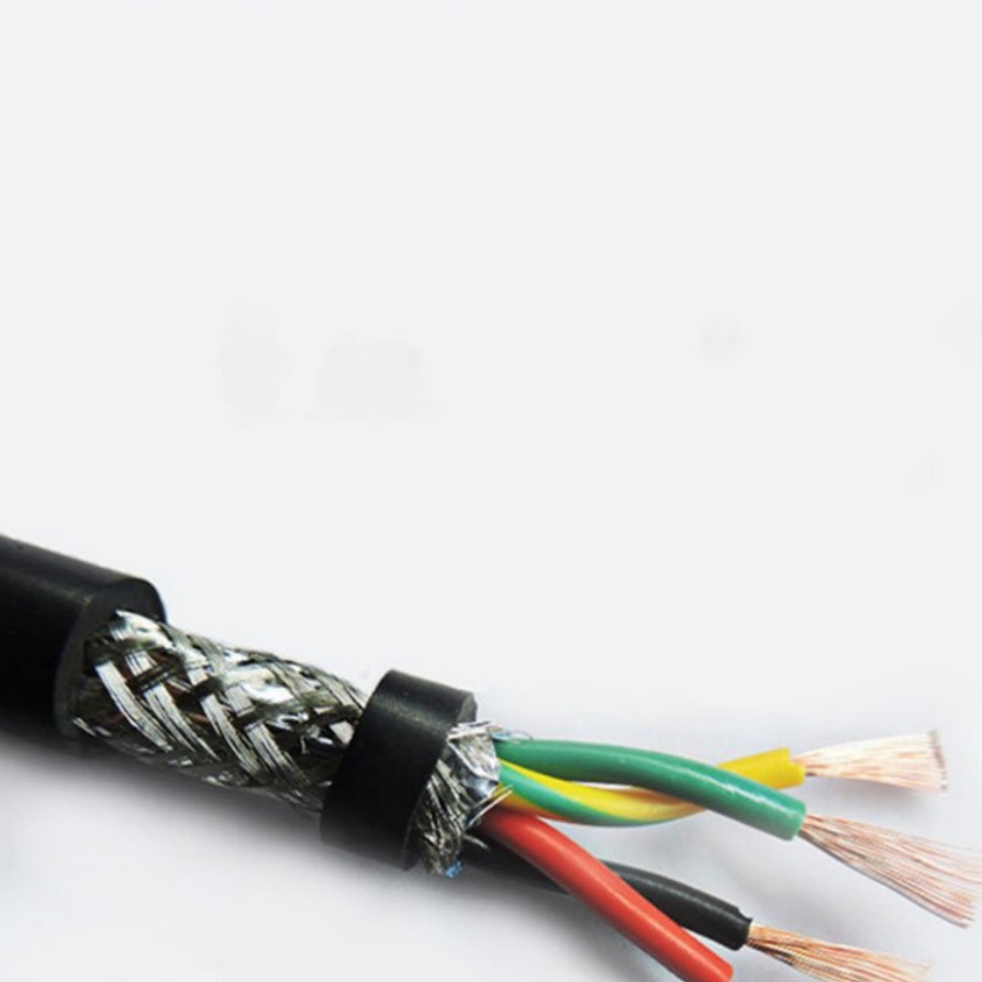
Opt for double-shielded cables (foil + braid) in high-noise environments.
Route cables away from power lines and rotating machinery.
5. Cost and Scalability
Problem: Long cables raise material costs and complicate cable management in large systems.
Solution:
Centralize processing units to minimize cable runs.
Use PoE (Power over Ethernet) to reduce separate power cables.
Best Practices for Determining Cable Length
Map the System Layout First
Design equipment placement to minimize cable runs while ensuring accessibility for maintenance.
Test with Prototype Lengths
Temporarily install longer cables during setup, then trim to the optimal length after finalizing positions.
Prioritize Standardized Interfaces
Choose vision components with compatible, industry-standard connectors (e.g., GigE Vision over proprietary options).
Leverage Active Components
Use repeaters, extenders, or fiber converters for systems requiring lengths beyond standard limits.
Case Studies: Cable Length Optimization in Action
Automotive Assembly Line
Challenge: Cameras monitoring weld quality required 25-meter cables spanning robotic cells.
Fix: Installed fiber optic cables with SFP modules to maintain 10 Gbps throughput without signal loss.
Pharmaceutical Packaging
Challenge: Short USB3 Vision cables limited camera positioning in a compact cleanroom.
Fix: Deployed active optical USB3 cables (15 meters) to retain high bandwidth and flexibility.
Drone-Based Inspection
Challenge: Tethered drones needed lightweight, flexible cables under 10 meters to avoid drag.
Fix: Used ultra-thin coaxial cables with reinforced strain relief for durability and minimal weight.


