Step-by-Step Guide to Installing Machine Vision Cables Safely
Machine vision systems are critical for precision tasks like automated inspection, robotic guidance, and real-time analytics. However, improper installation of vision cables can lead to signal degradation, equipment damage, or even safety hazards. Pre-Installation Preparation 1. Gather Tools and Materials Tools: Cable strippers/crimpers Multimeter for continuity testing Torque wrench (for industrial connectors) Cable ties and strain relief clamps Materials: Shielded machine vision cables (e.g., GigE Vision, CoaXPress, or USB3 Vision) EMI-resistant conduit (optional) Anti-static wrist straps Cable labels for identification
2. Review System Requirements Confirm the interface standard (e.g., CoaXPress 2.0, USB3 Vision) and maximum cable length per the camera and processor specifications. Check voltage/power requirements if using Power over Ethernet (PoE) or Power over Coax (PoC). 3. Assess the Environment Identify sources of electromagnetic interference (EMI) (e.g., motors, power lines). Plan routes to avoid sharp bends, heat sources, or moving machinery. Step 1: Power Down and Secure the System Turn off all connected devices (cameras, processors, robots) to prevent electrical surges. Disconnect power sources and use lockout/tagout (LOTO) procedures in industrial settings. Ground yourself with an anti-static wrist strap to avoid electrostatic discharge (ESD) damage. Step 2: Route the Cable Avoid High-EMI Zones: Keep cables ≥30 cm (12 inches) away from motors, inverters, or AC power lines. Use shielded conduit in environments with heavy interference (e.g., automotive assembly lines). Maintain Bend Radius: Follow the manufacturer’s bend radius (typically 10x the cable diameter). Example: A 6mm-diameter cable should not bend tighter than a 60mm radius. Secure Cables Properly: Use nylon cable ties or Velcro straps to fasten cables without over-tightening. Install strain relief clamps near connectors to prevent tugging. Step 3: Terminate Connectors Strip Insulation Carefully: Use a precision stripper to avoid nicking conductors. Expose only the necessary conductor length (refer to connector datasheets). Crimp or Solder Connectors: For industrial connectors (e.g., M12, BNC), use a torque wrench to ensure proper tightness. Verify polarity alignment (e.g., pin 1 to pin 1) for multi-conductor cables. Test Continuity: Use a multimeter to check for short circuits or open lines before powering up. Step 4: Grounding and Shielding Connect Shield Drains: Attach cable shields to grounded chassis points using pigtail wires or conductive tape. Ensure grounding paths are low-resistance (<1 ohm). Terminate Both Ends (for GigE/Coax): Ground shields at both ends to minimize ground loops in high-noise environments. Exception: Follow single-point grounding for systems sensitive to ground loops. Step 5: Verify Signal Integrity Power Up Gradually: Reconnect devices one at a time, starting with the processor. Test Signal Quality: Use diagnostic software (e.g., GenICam-compatible tools) to check for packet loss or latency. Inspect live video feeds for artifacts like pixelation or flickering. Measure EMI Impact: Use an oscilloscope to compare signal waveforms with/without nearby EMI sources. Step 6: Finalize and Document Label Cables: Tag both ends of each cable with unique IDs (e.g., “Cam01_to_Processor”). Update System Diagrams: Document cable routes, lengths, and grounding points for future maintenance. Conduct a Safety Audit: Ensure no exposed conductors, sharp edges, or trip hazards. Common Installation Mistakes to Avoid Ignoring Bend Radius: Tight bends cause signal loss or cable jacket cracks. Mixing Cable Types: Using non-shielded cables in high-EMI areas degrades performance. Poor Grounding: Floating shields invite noise; improper grounding creates loops. Overlooking Strain Relief: Unsupported connectors lead to premature failure. Maintenance Tips for Long-Term Reliability Inspect Quarterly: Check for abrasions, loose connectors, or corrosion. Clean Connectors: Use isopropyl alcohol and lint-free swabs to remove dust. Retest After Modifications: Verify signal integrity if machinery layout changes.
Subtitle: A High-Performance Signal Cable Designed for 3D Scanners, Ensuring Lossless Data and Minimal Latency
Product OverviewThe 3D Scanner Vision Signal Cable is a premium signal transmission cable engineered for both industrial a.
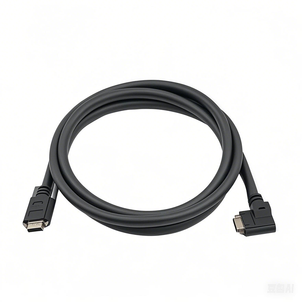
Product Overview: Machine Vision Cables
Machine vision cables are specialized components designed to ensure high-speed, stable data transmission and signal integrity in automated imaging systems. Key features include:
Technical S.
High-speed factories demand flawless synchronization between machines and vision systems. Yet, challenges like electromagnetic interference (EMI), cable fatigue, and data bottlenecks often disrupt operations. The right machine vision cab.
Meta Description: Discover premium Robotic Vision System Cables engineered for seamless data transmission, durability, and precision in industrial automation. Ensure flawless vision system performance.
Enhance Automation Precision with.
Meta Description: Discover the Flexible & Bend-Resistant Vision Cable, engineered for precision imaging in demanding environments. Durable, reliable, and built to last. Perfect for industrial, medical, and robotic applications.
Int.
Meta Description: Experience seamless 4K/8K video transmission with our High-Speed Anti-Interference Vision Cable. Engineered for crystal-clear visuals, robust durability, and interference-free performance. Perfect for gaming, profes.
Elevate your visual data transmission with the IP67 Waterproof Vision Connection Cable, engineered to deliver seamless performance in the harshest conditions. Designed for industrial, outdoor, and mission-critical applications, this rugg.
The Precision Imaging Dedicated Vision Cable is a cutting-edge connectivity solution designed to deliver crystal-clear image transmission in high-stakes environments. Optimized for industrial automation, medical imaging, machine vision, .
Enhance the reliability and performance of your automated systems with our Industrial-Grade Machine Vision Cable—engineered to deliver unparalleled signal integrity, durability, and speed for demanding industrial applications. Designed f.
Shielded Twisted-Pair Vision Cable – Ultra-Clear Signal Transmission for Demanding Environments
Ensure flawless video and data transmission in high-interference environments with our Shielded Twisted-Pair (STP) Vision Cable. Engineere.