Fixing Pixelation Errors Caused by Faulty Machine Vision Cables: A Co...
Is your production line plagued by blurry, blocky, or distorted images from your machine vision cameras? Are failed inspections, costly rework, or unexpected downtime becoming routine? While it’s easy to blame the camera or the software, a surprisingly common culprit hiding out of sight is often at fault: faulty machine vision cables.
In high-stakes industrial automation and quality control, pixelation errors aren’t just annoying; they lead to false rejects, missed defects, and significant financial losses. Understanding how cables cause these issues and how to fix them is crucial for maintaining peak system performance. This guide dives deep into diagnosing, resolving, and preventing cable-induced pixelation.
Understanding the Link: How Faulty Cables Cause Pixelation
Machine vision systems rely on high-speed data transfer from cameras to processors via cables (commonly GigE Vision, USB3 Vision, or Camera Link). When these cables degrade or malfunction, the digital signal carrying image data becomes corrupted. Instead of clean, clear pixels reaching the host computer, the result is often:
- Blocky Artifacts (“Pixelation”): Individual pixels or blocks of pixels appear distorted, misplaced, or colored incorrectly.
- Static or “Snow”: Random colored speckles appear across the image.
- Partial Image Loss: Sections of the image are missing or garbled.
- Horizontal or Vertical Lines: Obvious streaks running through the image.
- Complete Signal Drop: The image disappears entirely.
This corruption stems primarily from:
- Physical Damage: Crushing, kinking, excessive bending (especially at connectors), cuts, or frayed wires internal to the cable. This physically breaks signal paths.
- Failing Connectors: Loose connections, bent pins, oxidized contacts, or internally broken solder joints within the connectors themselves. This introduces intermittent contact points.
- EMI/RFI Interference: Poor shielding in the cable allows electromagnetic interference (EMI) from motors, drives, relays, or even nearby high-power cables to corrupt the digital signal. This is a major cause of seemingly random pixelation.
- Signal Integrity Degradation: Over time, factors like impedance mismatch, high signal attenuation (signal loss over length), or crosstalk between wires within the cable can degrade the signal quality to the point where the receiving device can’t correctly interpret the data, leading to errors.
- Incorrect Cable Specification: Using a cable not rated for the required bandwidth, length, or environment (e.g., insufficient shielding for an EMI-heavy area). **”It was lying around” cables are often the root of the problem.**
Diagnosing Cable-Induced Pixelation: Step-by-Step
Don’t replace components blindly! Follow these diagnostic steps:
- Inspect Visually: Carefully examine the entire length of the cable and connectors.
- Look for obvious physical damage: kinks, crushing, cuts, exposed wires.
- Check connectors: Are they securely seated? Any bent, broken, or oxidized pins? Any signs of corrosion or internal damage? Ensure locking screws/levers are tight.
- Is the cable strained? Is it bending too sharply near connectors (min. bend radius violation)?
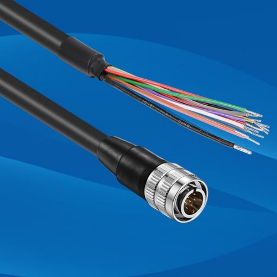
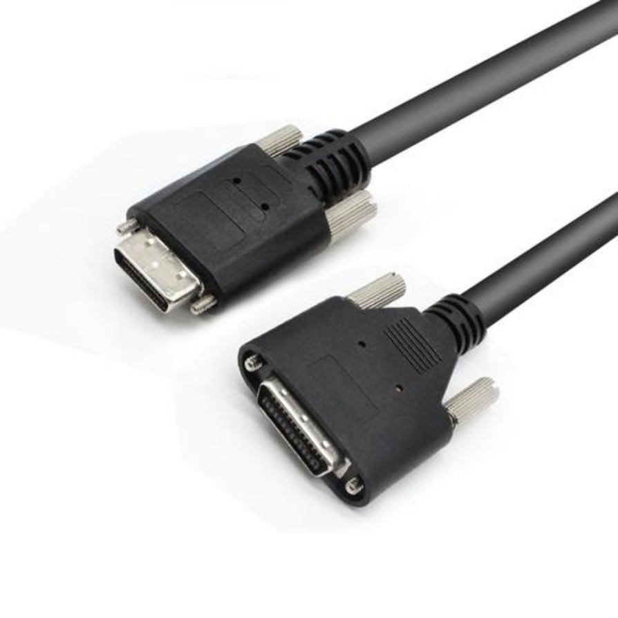
- Is the cable type correct? Verify it matches the Camera Interface standard (e.g., GigE Cat 6, USB3 Gen1, Camera Link Deca) and the required bandwidth/length.
- Check the Environment:
- Is the cable routed near strong EMI sources (motors, VFDs, welders, power lines)?
- Is the cable subjected to excessive vibration or mechanical stress?
- Is the environment unusually hot, cold, humid, or chemically harsh? Standard cables have limitations.
- Perform the “Wiggle Test”:
- Gently manipulate the cable along its length and near the connectors while the system is running and displaying an image.
- Does the pixelation appear, worsen, change, or disappear as you manipulate specific sections? This pinpoints the problem area.
- Substitution is Key (The Easiest & Most Reliable Test):
- Replace the suspect cable with a known-good, high-quality cable of the correct specification.
- If the pixelation vanishes, you’ve confirmed the original cable was faulty. This is the gold standard diagnostic method.
- Utilize Software Tools (If Available):
- Some camera software SDKs offer diagnostic tools for signal integrity or error counts (e.g., packet errors in GigE Vision).
Solutions: Fixing and Preventing Cable-Related Pixelation
Once a faulty cable is diagnosed:
- Replace the Cable: This is the most reliable and permanent solution. Crucially:
- Buy High-Quality: Invest in cables from reputable machine vision suppliers (e.g., Matrox, Basler, Flir, Stemmer Imaging, TKH Vision). Avoid generic “off-the-shelf” cables not designed for industrial vision demands.
- Match Specifications: Ensure the cable matches your camera interface, bandwidth needs, and required length.
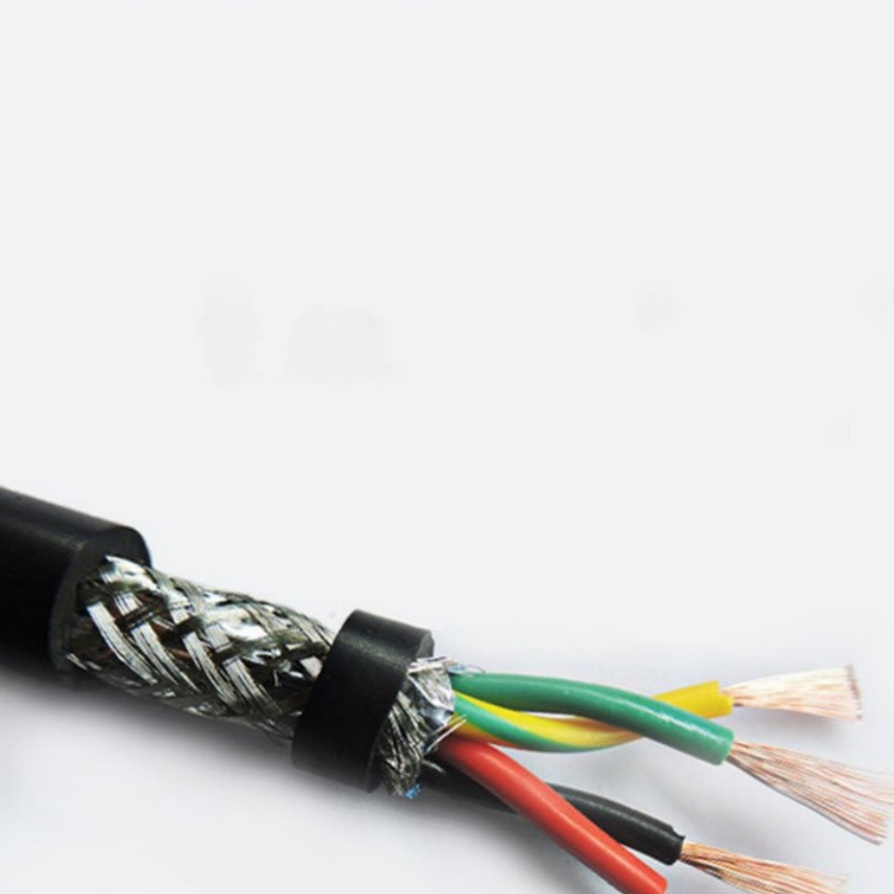
- Choose the Right Shielding: For EMI-prone environments, double-shielded cables (e.g., S/FTP for GigE) are essential. Metalized connector shells provide better EMI protection than plastic.
- Consider Environment: Use cables with appropriate jackets (e.g., PUR for oil/chemical resistance, TPE for flexibility) and operating temperature ranges. Use flex-rated cables in constant motion robots.
- Temporary Fixes (Use with Caution):
- Secure Loose Connectors: If a loose connection was the issue, ensure it’s firmly seated and locked. Avoid repeated unplugging/replugging. Monitor closely.
- Reroute Away from EMI: Temporarily move the cable away from obvious noise sources if safely possible. This might reduce interference while you procure a better-shielded replacement.
- WARNING: These are temporary measures until a proper cable replacement arrives. They do not address underlying cable damage or inherent signal integrity issues.
Prevention: Stopping Pixelation Before It Starts
Proactive measures save downtime:
- Invest in Quality Cables from the Start: View cables as critical components, not commodities. High-quality shielded cables cost more upfront but prevent vastly more expensive failures.
- Proper Installation & Strain Relief:
- Avoid tight bends exceeding the cable’s minimum bend radius, especially at connectors. Use cable guides or strain relief boots/clamps.
- Ensure adequate slack to prevent pulling on connectors.
- Securely anchor cables at regular intervals to minimize vibration stress.
- Shielding & Grounding Best Practices:
- Choose shielded cables appropriately for the environment.
- Ensure proper grounding of cable shields, typically at the host end according to the camera/cable specification. Bad grounding renders shielding ineffective.
- Physically separate vision cables from high-power cables and EMI sources whenever possible (cross at 90 degrees if unavoidable).
- Regular Inspection & Maintenance:
- Visually check cables and connectors periodically for damage, wear, or looseness.
- Add cable inspection to your preventative maintenance schedule.
- Label and Document: Clearly label vision cables at both ends. Document their specifications and installation paths for easier troubleshooting.
- Manage Cable Movement: In robotics or moving applications, use proper energy chains (cable carriers) designed to manage repetitive motion without damaging cables.
Real-World Impact: Case Study Example
A major automotive parts manufacturer faced intermittent pixelation errors on their final inspection cameras, causing an unacceptable 5% false reject rate. Technicians initially suspected cameras and recalibrated multiple times with no improvement. Following the diagnostics above, they observed pixelation worsening when vibration increased near a large stamping press. The “wiggle test” near the Camera Link cable connector caused immediate image corruption. Replacing the standard cable with a high-flex, double-shielded cable designed for high-vibration EMI environments completely eliminated the pixelation and restored inspection accuracy to 99.98%, saving thousands in lost production and rework per month.


