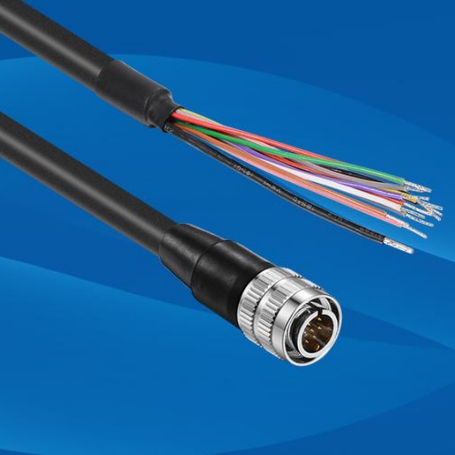
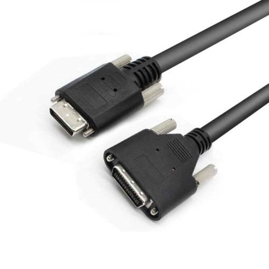
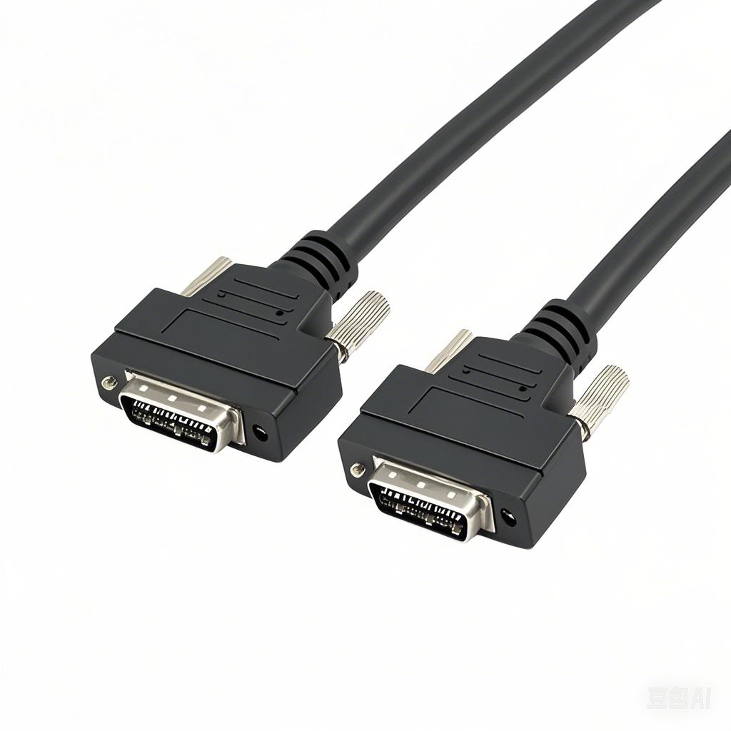
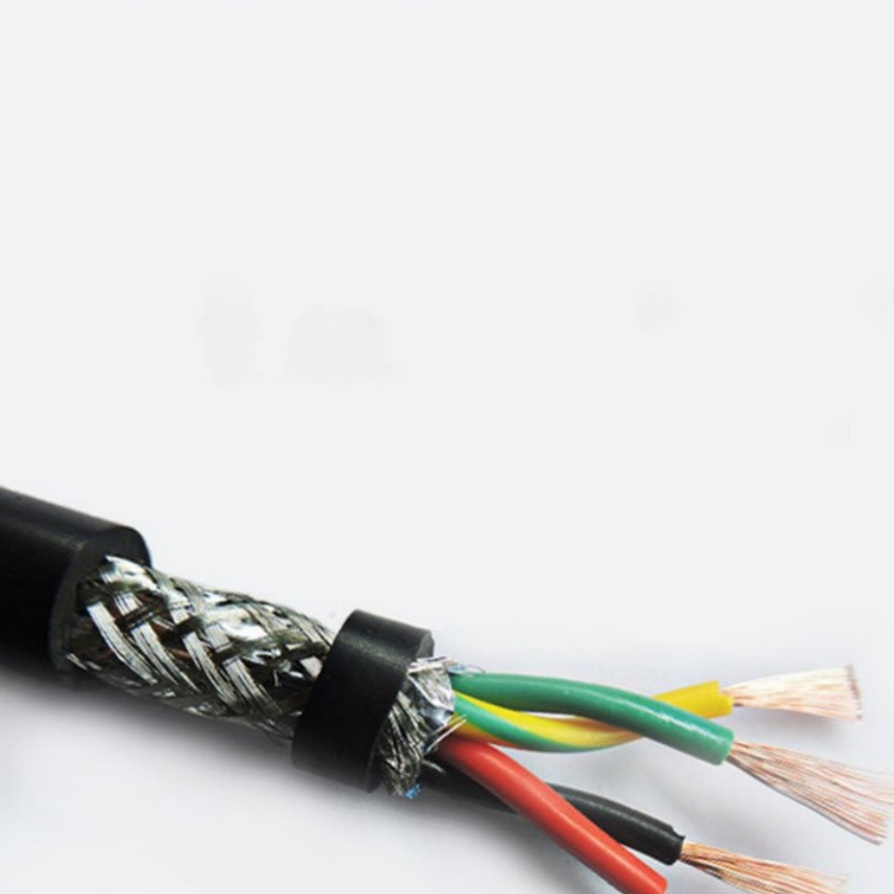
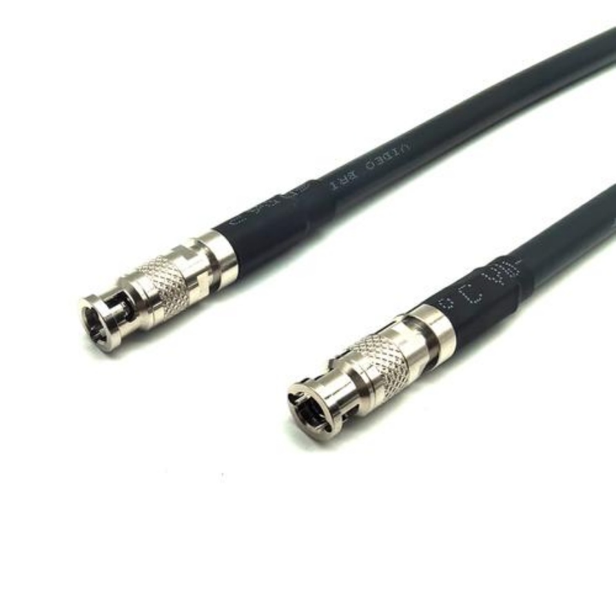
Seeing Problems Clearly: Machine Vision Cables with Diagnostic LEDs
In the fast-paced world of factory automation, every second of unexpected downtime costs money. Machine vision systems – the high-tech “eyes” guiding robots, inspecting products, and ensuring quality – are critical. But when an image suddenly goes dark or flickers, pinpointing the fault can be frustrating and time-consuming. Was it the camera? The light? The software? Or… the cable?
This is where Machine Vision Cables with Diagnostic LEDs become absolute game-changers. These aren’t your ordinary cables; they’re intelligent assistants built into the connection itself, designed to give you immediate visual clues about what’s happening.
Why Standard Cables Are Like a Black Box
Traditional high-quality machine vision cables (like USB3 Vision, GigE Vision, CoaXPress) are essential, but they offer no external indication of their status. When an image feed disappears:
- Is power reaching the camera? You might need a multimeter to check.
- Is there a physical link? No light means guessing.
- Is data actually flowing? Software tools might show errors, but doesn’t isolate the problem.
- Where is the break? Is it near the camera, the PC interface, or somewhere in between? You could be swapping cables blindly.
This diagnostic guessing game eats up valuable production time.
How Diagnostic LED Cables Illuminate the Problem (Literally!)
Integrating LED indicators directly onto the cable connectors provides instant, visual feedback:
- Power Status (Often Green):
- Solid Green: Healthy power is being delivered from the host (frame grabber/PC) to the camera.
- Off: No power detected. Points immediately to a power supply issue, host port problem, or upstream cable fault.
- Link/Activity Status (Often Amber/Yellow or Green):
- Solid Light: A physical communication link has been successfully established between the cable ends (e.g., GigE link up).
- Blinking Light: Data is actively being transmitted over the link. It’s the cable’s “heartbeat.”
- Off: No physical link established. Signals a connection problem at one end or the other, or potentially a faulty cable segment.
Key Benefits: Saving Time, Money, and Frustration
- Faster Troubleshooting: Immediately identify if the problem is power-related (LED off), a connection issue (Link LED off), or potentially downstream (if Link and Activity show good status, the issue might be camera/software/host).
- Reduced Downtime: Cut diagnostic times from minutes (or hours) down to seconds. Get the line moving again faster.
- Easier Maintenance: Technicians don’t need deep expertise or specialized tools for basic cable checks. Visual indicators are intuitive.
- Prevent Unnecessary Swaps: Avoid replacing potentially good cameras, frame grabbers, or cables based on guesswork. Confirm power and link status first.
- Localize the Fault: Seeing which LED isn’t lit helps narrow down where the problem lies (source end, camera end, or the cable run itself).
Where Are These Smart Cables Most Valuable?
- Complex or Hard-to-Reach Installations: Cables routed inside machines, under conveyors, or through cable carriers are prime suspects during faults. Diagnostic LEDs allow checking status without physical access.
- High-Value or Critical Production Lines: Minimizing downtime is paramount for profitability.
- Systems with Multiple Cameras: Quickly identify which specific camera/cable pair is causing an issue.
- Preventive Maintenance Checks: Quickly verify connections and power during routine checks before problems arise.
Important Considerations
- Not a Magic Bullet: They don’t diagnose software configuration issues, camera sensor faults, or complex electrical noise problems. They report on the fundamental health of the power and physical data link via the cable.
- Interpreting Lights: Always check the cable manufacturer’s documentation. While green-for-power and amber/link-activity are common, specific labeling or colors can vary slightly.
- Quality Still Matters: Diagnostic LEDs are an additional feature. The cable itself must still meet the required electrical and mechanical specifications (bandwidth, shielding, flex life, connectors) for your machine vision application. Don’t sacrifice core performance.
- Safety First: When troubleshooting, always follow proper lockout/tagout procedures. Never disconnect or manipulate cables while machinery is operating or energized unless explicitly safe to do so.
The Bottom Line
Machine Vision Cables with Diagnostic LEDs transform a passive component into an active troubleshooting partner. By providing clear, instant visual feedback on power and data link status, they empower technicians and engineers to identify and resolve common connectivity issues dramatically faster. This translates directly to reduced machine downtime, lower maintenance costs, and increased operational efficiency.
In the complex ecosystem of a machine vision system, clarity is key. Diagnostic LED cables bring crucial clarity to the connection, helping you keep your production lines running smoothly.
Checklist When Evaluating Diagnostic LED Cables:
- Core Performance: Does it meet the bandwidth & protocol (USB3 Vision, GigE Vision, CXP, etc.) requirements?
- Durability: Does it have the necessary shielding, flex rating, and robust connectors for your environment?
- Clear LED Indicators: Are the LEDs easy to see and understand (documented meaning)? Are they positioned for visibility in your setup?
- Reputable Brand: Choose established manufacturers known for reliable machine vision cables.
- Value: Does the potential time savings outweigh the typically small price premium over standard cables?
Investing in cables with diagnostic intelligence is a smart move for anyone relying on mission-critical machine vision systems. See the problem clearly, fix it faster.


