How to Connect Machine Cable to a Motor
Connecting a machine cable to a motor is a critical task in industrial setup, machinery maintenance, and equipment installation. Done correctly, it ensures efficient power transmission, reduces downtime, and minimizes safety risks. Done incorrectly, it can lead to motor failure, electrical hazards, or even operational shutdowns. This guide will walk you through the step-by-step process of connecting a machine cable to a motor, highlighting key considerations, best practices, and the role of high-quality machine cable in ensuring a reliable connection.
Understanding the Basics: Machine Cable and Motor Compatibility
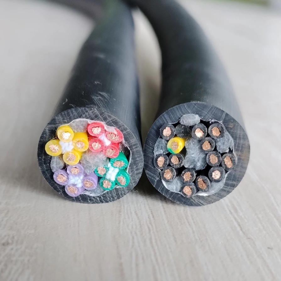
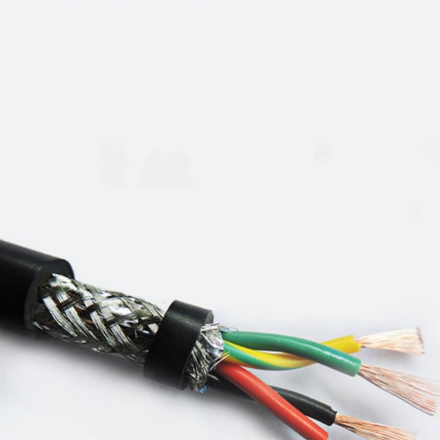
Before diving into the connection process, it’s essential to understand the relationship between machine cables and motors. A machine cable is a heavy-duty electrical cable designed to transmit power or signals between machinery components, including motors. These cables are built to withstand harsh industrial environments—resisting heat, oil, moisture, and physical abrasion.
Motors, on the other hand, come in various types (AC, DC, servo, etc.) and sizes, each with specific power requirements. The machine cable used must match the motor’s voltage, current, and environmental conditions. Using an incompatible cable—for example, one with insufficient current-carrying capacity—can cause overheating, insulation breakdown, or even fire.
Key specifications to check for compatibility:
- Voltage rating: The cable must handle the motor’s operating voltage (e.g., 120V, 240V, 480V).
- Current capacity (ampacity): The cable’s gauge (thickness) must support the motor’s full-load current. A thicker gauge (lower AWG number) carries more current.
- Insulation type: Choose insulation (PVC, rubber, Teflon) based on the environment—oil-resistant for factory floors, heat-resistant for high-temperature zones.
- Flexibility: For motors with moving parts, a flexible machine cable prevents fatigue and breakage.
Step-by-Step Guide to Connecting Machine Cable to a Motor
1. Prepare Tools and Safety Equipment
Safety is paramount when working with electrical components. Gather the following tools and equipment before starting:
- Insulated screwdrivers and pliers
- Wire strippers (adjustable for the cable gauge)
- Voltage tester (to confirm power is off)
- Heat shrink tubing or electrical tape
- Cable clamps or strain reliefs
- Work gloves and safety glasses
Ensure the work area is dry, well-lit, and free of flammable materials.
2. Power Off and Lockout/Tagout
Never work on a live motor. Locate the main power source for the motor and turn it off. Use a lockout/tagout (LOTO) system to prevent accidental power restoration—attach a lock and tag to the power switch indicating that work is in progress. Verify the power is off using a voltage tester on the motor’s terminals.
3. Inspect the Machine Cable and Motor Terminals
Examine the machine cable for damage: cracks in insulation, frayed wires, or corrosion. A damaged cable must be replaced to avoid short circuits. Next, check the motor’s terminals—they may be labeled (e.g., “L1,” “L2,” “L3” for three-phase motors, or “+,” “-” for DC motors) and could be screw-type, clamp-type, or terminal blocks.
Clean the motor terminals with a dry cloth to remove dirt or oxidation, which can hinder conductivity.
4. Measure and Cut the Machine Cable
Measure the distance between the motor and the power source or control panel to determine the required cable length. Add a few inches of slack to avoid tension on the connection. Use a sharp utility knife to cut the machine cable to length, taking care not to nick the inner conductors.
5. Strip the Cable Insulation
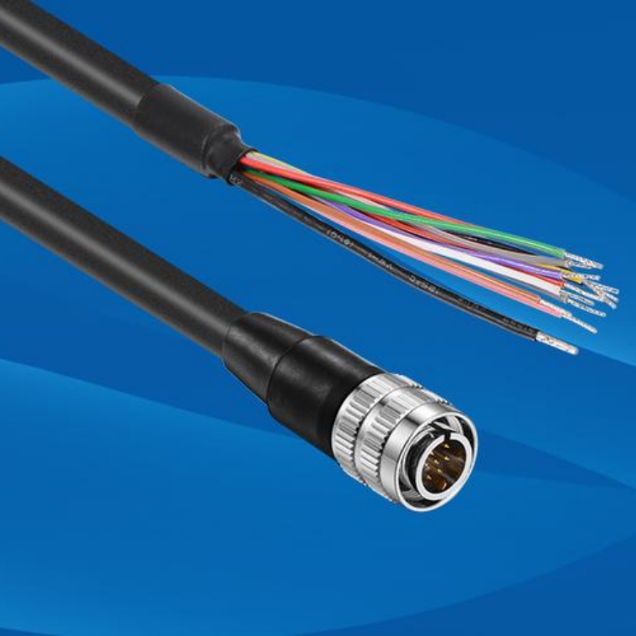
Using wire strippers, carefully remove ½ to ¾ inch of the outer insulation from the end of the machine cable. This exposes the inner conductors (typically copper or aluminum). Avoid cutting into the conductor itself, as this weakens the wire and reduces conductivity.
If the cable has multiple conductors (common in three-phase motors), strip ¼ inch of insulation from the end of each individual wire. Twist the strands of each conductor tightly to prevent fraying.
6. Connect the Cable to the Motor Terminals
Refer to the motor’s wiring diagram (usually found on a label attached to the motor) to identify which terminal corresponds to each conductor. For single-phase motors, you’ll typically connect the “hot” (black or red) and “neutral” (white) wires to their respective terminals, plus a ground wire (green or bare) to the motor’s ground terminal. For three-phase motors, connect each phase conductor (often labeled L1, L2, L3) to the matching terminals.
Secure the conductors to the terminals:
- For screw-type terminals: Loop the stripped end of the wire clockwise around the screw, then tighten the screw firmly. Ensure no stray strands are left exposed.
- For clamp-type terminals: Insert the stripped wire into the clamp, then tighten the clamp screw until snug.
- For terminal blocks: Insert the wire into the block and secure with the locking mechanism (screw or spring).
Always connect the ground wire first (if applicable) to reduce the risk of electric shock.
7. Insulate and Protect the Connection
After securing the wires, insulate any exposed conductors using heat shrink tubing (preferred for durability) or electrical tape. Heat shrink tubing provides a tight, moisture-resistant seal—slide it over the connection, then use a heat gun to shrink it into place.
For added protection, install a strain relief fitting where the machine cable enters the motor housing. This prevents the cable from being pulled or twisted, which can loosen connections over time.
8. Test the Connection
Once the connection is complete, remove the lockout/tagout device and restore power to the motor. Use a voltage tester to confirm power is reaching the motor terminals. Start the motor briefly to check for unusual noises, overheating, or vibrations—these may indicate a loose connection.
If the motor operates smoothly, turn it off again and perform a final inspection: check that all terminals are tight, insulation is intact, and the cable is secured with strain relief.
Common Mistakes to Avoid
- Using the wrong cable gauge: Undersized cables overheat; oversized cables are costly and inflexible.
- Poor insulation: Exposed wires risk short circuits or electric shock.
- Ignoring environmental factors: A non-oil-resistant cable in a machine shop with hydraulic fluids will degrade quickly.
- Over-tightening terminals: This can damage conductors or strip screws.
- Skipping the ground connection: Grounding prevents electric shock and protects equipment from voltage surges.
Why Quality Machine Cable Matters
The reliability of your motor connection depends heavily on the quality of the machine cable. High-quality cables are manufactured with precise conductor stranding, durable insulation, and consistent thickness—ensuring optimal conductivity and resistance to wear. They meet industry standards (e.g., UL, IEC) for safety and performance, reducing the risk of failures in critical operations.
Trust FRS for Your Machine Cable Needs
When it comes to connecting machine cables to motors, the right cable makes all the difference. At FRS, we specialize in manufacturing premium machine cables designed for industrial durability and performance. Our cables are engineered to meet strict voltage, ampacity, and environmental standards—whether you need oil-resistant cables for factory floors, heat-resistant options for high-temperature motors, or flexible cables for moving components.
FRS factory prioritizes quality at every step: from selecting high-grade copper conductors to testing each batch for insulation integrity and conductivity. We offer a range of gauges and insulation types to match any motor specification, ensuring a seamless, long-lasting connection.
For reliable machine cables that keep your motors running efficiently and safely, choose FRS. Trust in our expertise to power your operations—today and for years to come.


