How to Properly Ground Machine Vision Cables: Avoid Glitches & E...
Machine vision systems are the eyes of modern automation, performing critical tasks like inspection, measurement, and guidance with incredible speed and precision. But even the best cameras and software can be crippled by one common culprit: improper cable grounding. Electrical noise interference can cause flickering images, random resets, inaccurate readings, or total system failure. Grounding your cables correctly is not optional; it’s essential for reliable performance.
Why Grounding Machine Vision Cables Matters
Machine vision cables (especially those carrying power and high-speed digital signals like Camera Link, CoaXPress, GigE Vision, or USB3 Vision) act like antennas. They can pick up electromagnetic interference (EMI) from motors, drives, relays, welding equipment, or even fluorescent lights nearby. This electrical “noise” gets superimposed onto the delicate signals traveling to and from your camera, corrupting the data.
Proper grounding provides a safe, low-resistance path for this unwanted electrical noise to flow harmlessly away from your sensitive vision components and back to earth, rather than through your signal wires. It prevents:
- Image Flickering/Noise: Static, snow, or shifting lines in your images.
- System Instability: Camera freezes, unexpected resets, or communication dropouts.
- Measurement Errors: Subtle noise causing inaccurate part positioning or inspection failures.
- Equipment Damage: In severe cases, voltage spikes can damage camera sensors or frame grabbers.
How to Ground Machine Vision Cables Properly: A Step-by-Step Guide
Here’s how to establish effective grounding for your vision cables:
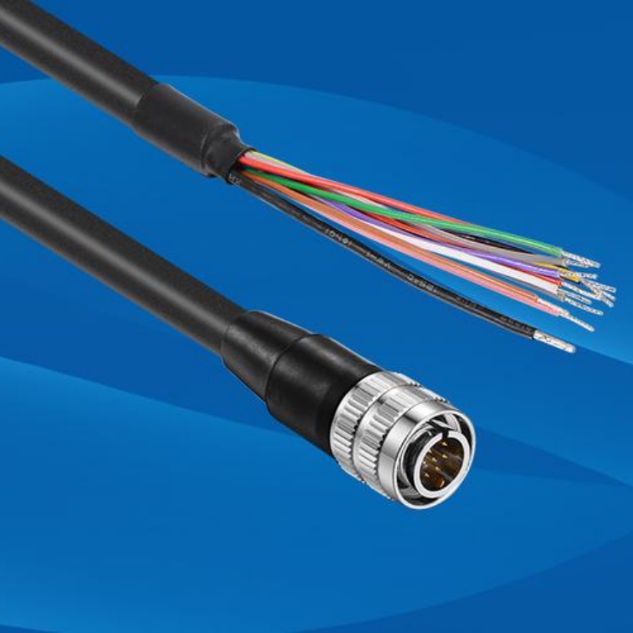
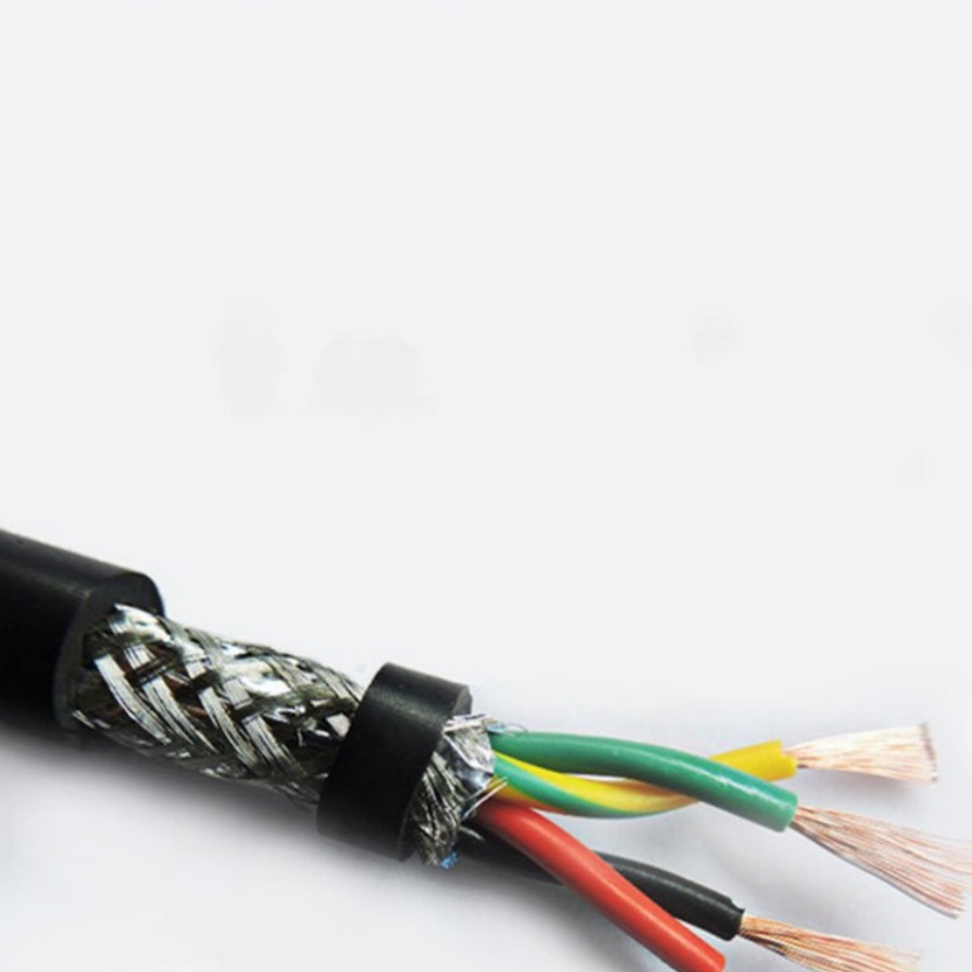
- Use Shielded Cables: This is non-negotiable. High-quality machine vision cables come with an electrically conductive shield layer (usually braided copper or foil) surrounding the inner signal/power conductors. This shield is the heart of your grounding strategy.
- Connect the Shield at ONE End Only (Usually the Controller/FG Side):
- Best Practice: Connect the cable shield directly to the grounding terminal (often labeled “GND”, “Earth”, or shield symbol) on your frame grabber, power supply unit, or vision controller. Use the dedicated grounding screw or terminal provided.
- Avoid Shield Loops: NEVER connect the shield to ground at both ends (camera AND controller). This creates a “ground loop” – a conductive path forming a large loop antenna that actually picks up more noise instead of draining it. Connecting only at the controller/frame grabber end is standard practice.
- Ensure Low-Impedance Ground Connection:
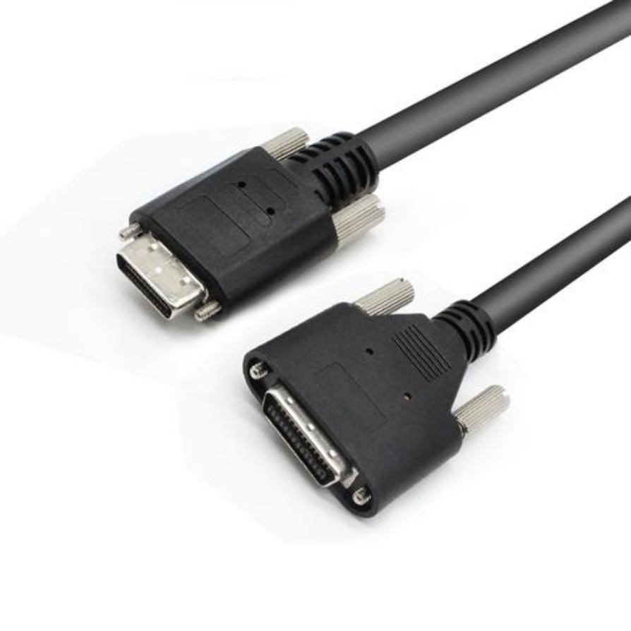
- Use Proper Terminations: If your cable has a connector hood with a grounding screw or clamp specifically for the shield, use it! Ensure the connection point is clean (free of paint, oxidation) and tight.
- Direct Metal Contact: The shield connection point on the cable connector must make clean, solid contact with the grounded metal part of the receiving device (frame grabber chassis, power supply chassis).
- Short Ground Straps (If Needed): Some connectors may require a short, braided grounding strap between the connector hood and the grounded chassis of the receiving device. Ensure these straps are intact and tightly secured at both ends.
- Ground the Vision System Components Themselves:
- Frame Grabber/Controller/Power Supply: These must be properly grounded via their mains power connection (using a grounded 3-prong AC power cable plugged into a grounded outlet). Verify the chassis potential is earth ground using a multimeter if uncertain.
- Camera Housing: Many industrial cameras have a metal housing with a dedicated grounding terminal. Connect this directly to the machine chassis ground using a short, thick wire (e.g., 18 AWG or thicker). Do not daisy-chain grounds; connect each camera directly to the central ground point. This path provides safety grounding and helps shunt noise away from the camera electronics.
- Lighting Power Supplies: Ground them robustly via their AC input and ensure their low-voltage DC outputs (to the lights) have their negative terminals connected back to the same system ground.
- Establish a Central Grounding Point (Star Point):
- For complex systems, use a central grounding bus bar or terminal strip connected directly to the building’s earth ground (like a grounding rod or verified building steel). Ground all key components (vision controller, PLC, VFD drives, lighting supplies, camera bodies) directly to this single point. This minimizes ground potential differences between components, which are a major source of noise.
Critical Mistakes to Avoid
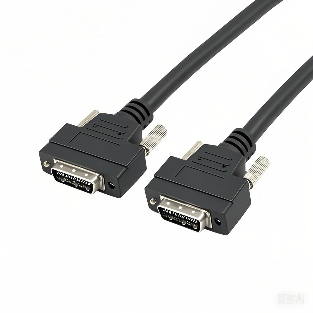
- Relying Only on Pin 1/Ground Conductor: Don’t assume the ground wire inside the cable (e.g., Pin 1 in MDR connectors) is sufficient for the shield’s job. The shield needs its own direct chassis connection. Often the internal ground wire is meant for signal reference, not EMI protection.
- Floating Shields: Leaving the cable shield disconnected at both ends makes it useless against noise; it becomes a very efficient antenna.
- Ground Loops: Created by connecting shields or equipment grounds at multiple points with differing potentials. Stick to the “single point” principle.
- Poor Shield Termination: Crimping instead of soldering to a proper clamp, dirty connections, loose screws, or painted surfaces under the ground lug all ruin the connection.
- Daisy-Chaining Component Grounds: Always go back to the central point.
- Ignoring Camera/Lighting Grounding: Every active component needs its own safety/protective earth ground connection.
Tools You Might Need
- Multimeter (to check ground continuity and potentials)
- Screwdrivers (appropriate sizes for grounding screws/clamps)
- Wire strippers/crimpers (if attaching grounding wires)
- Short lengths of insulated grounding wire (green or green/yellow, appropriate gauge)
- Soldering iron (if specified for shield termination)
- Contact cleaner (for ensuring clean metal-to-metal contact)
Conclusion: Grounding = Reliability
Taking the time to ground your machine vision cables and components correctly is an investment in system stability and accuracy. By providing a dedicated, low-impedance path for electrical noise to escape, you protect your delicate image data from corruption. Remember the core principles: use shielded cables, connect the shield properly at ONE end (controller side), establish solid ground connections for all equipment, and use a central grounding point. Following these steps will significantly reduce noise-related headaches and ensure your machine vision system performs flawlessly day in and day out.


