How to Repair Damaged Machine Vision Cables: A Practical Guide for In...
Machine vision cables are the vital nervous system connecting cameras, sensors, lights, and controllers in automated systems. When damaged, they cause costly downtime, misreads, and production headaches. Knowing how to assess and repair them safely is an essential industrial skill. Here’s a detailed, step-by-step guide based on best practices.
Why Repairing These Cables is Critical (and Tricky):
- High Cost: Replacement cables, especially proprietary or long-length ones, are expensive.
- Lead Times: Waiting for new cables halts production.
- Complexity: Often carry power, multiple data signals (GigE, CoaXPress, Camera Link), and sometimes lighting control – increasing repair complexity.
- Fragility: Internal wires are fine, shielding is delicate, connectors are precision parts.
Step 1: SAFETY FIRST & Initial Assessment
- Power Down: Always disconnect all power sources upstream (PLC, power supply) and downstream (camera, light) before touching any cables or connectors. Verify zero voltage.
- Isolate the Damage: Visually inspect the entire cable run. Look for:
- Obvious cuts, crushing, or abrasion on the outer jacket.
- Kinks or sharp bends (especially near connectors).
- Melted or deformed sections.
- Damaged or bent connector pins/housings.
- Corrosion (liquid ingress).
- Identify the Cable Type: Determine if it’s:
- Power Cable: For cameras/lights (usually simpler, fewer conductors).
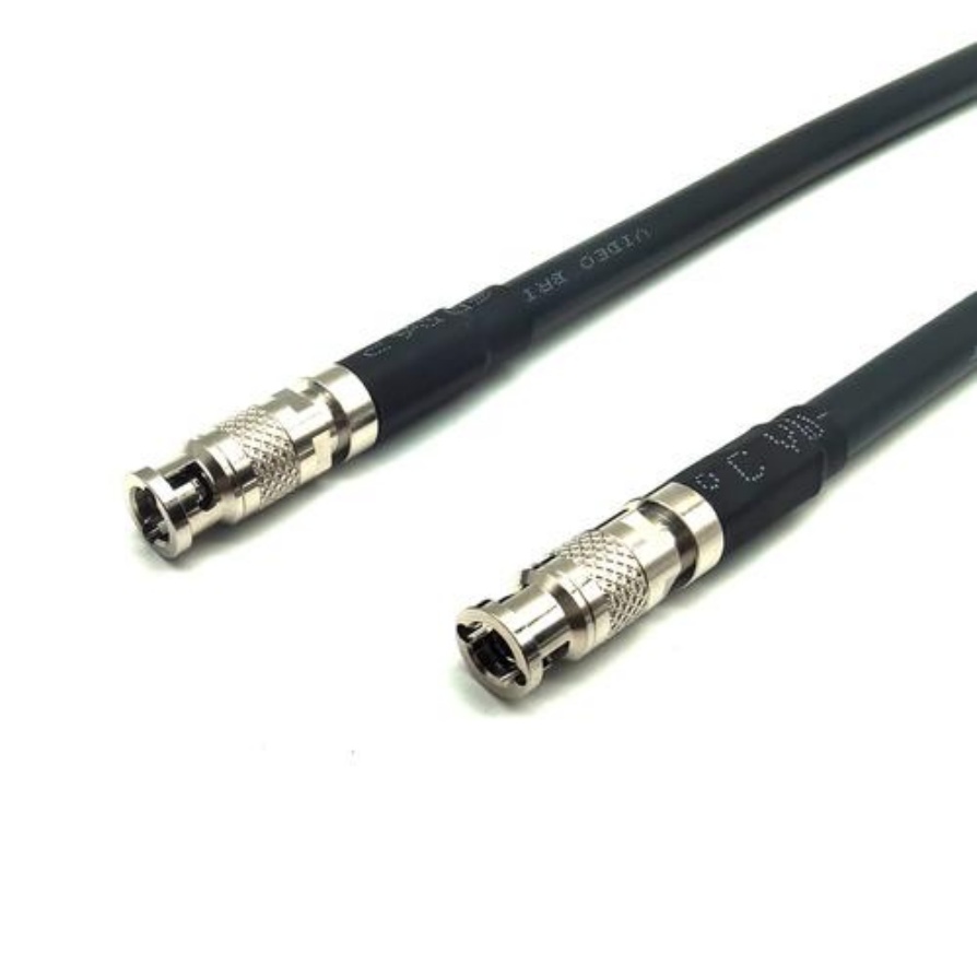
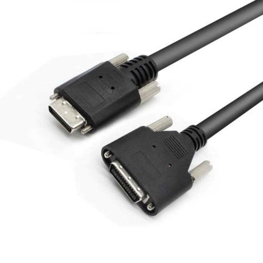
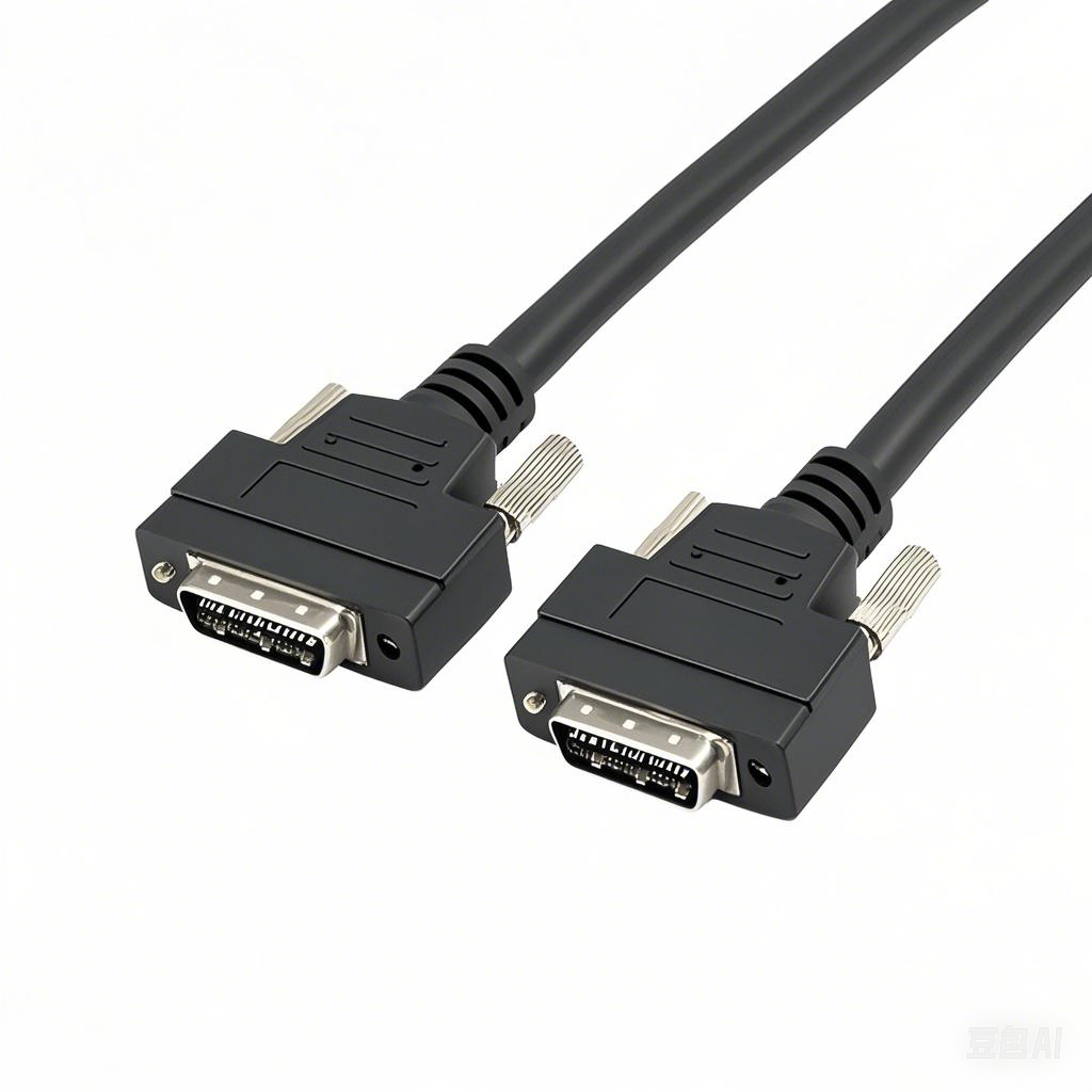
- Data Cable: GigE Vision (Ethernet), USB3 Vision, CoaXPress, Camera Link.
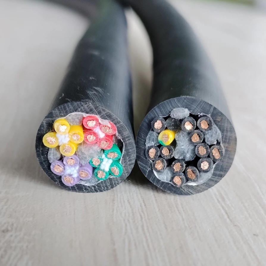
- Hybrid Cable: Combines power + data (+ sometimes lighting control/I/O).
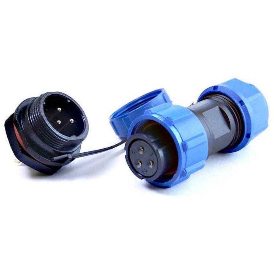
- Connector Types: M8, M12 (A/B/C/D/X-coded), RJ45, Fischer, proprietary variants. Coding matters! (e.g., X-coded for GigE).
Step 2: Diagnosing the Extent of Damage
- Visual Inspection (Detailed): Use good lighting and magnification if needed. Look inside connectors for bent pins, debris, or moisture.
- Continuity Test (Multimeter):
- Test each internal conductor from one end to the other (Ohms mode – expect near 0Ω).
- Test each conductor against shield/ground and against other conductors (should be infinite/open circuit, indicating no shorts).
- Critical: Check shield continuity from connector shell to connector shell.
- Insulation Resistance Test (Megohmmeter – Optional but Recommended): Especially if moisture or chemical exposure is suspected. Tests the integrity of the insulation between conductors and shield. Low readings indicate potential failure.
- Data Communication Test (If Possible): After ensuring basic continuity/power is good, reconnect only power and see if the device powers. Then test data communication. Use vendor software to check for packet loss or errors.
Step 3: Making the Repair Decision
- When Repair is Feasible:
- Localized damage away from connectors (clean cut, abrasion).
- Damaged connector that can be cleanly replaced.
- One or two damaged wires within a repairable section.
- When REPLACEMENT is Mandatory:
- Damage close to or within a molded connector body.
- Severe crushing over a long section.
- Evidence of liquid ingress along the cable length.
- Damaged foil or braided shield over a large area.
- Damage to the cable’s structural integrity (bending element, multiple broken fibers in fiber optic hybrid cables).
- Repair cost/time approaches or exceeds replacement cost/downtime.
Step 4: How to Repair Damaged Cables (Common Scenarios)
- Replacing a Connector:
- Identify the Exact Connector: Match the shell size (e.g., M12), coding (e.g., D-coded for USB3, X-coded for 10GigE), pin count, and gender precisely. Mismatches won’t work.
- Acquire a Replacement Kit: Includes shell, insert, pins/sockets, seals, strain relief boots. Use the correct crimp tool & dies for the pins. This is non-negotiable.
- Cut the Damaged Connector: Leave as much good cable as possible.
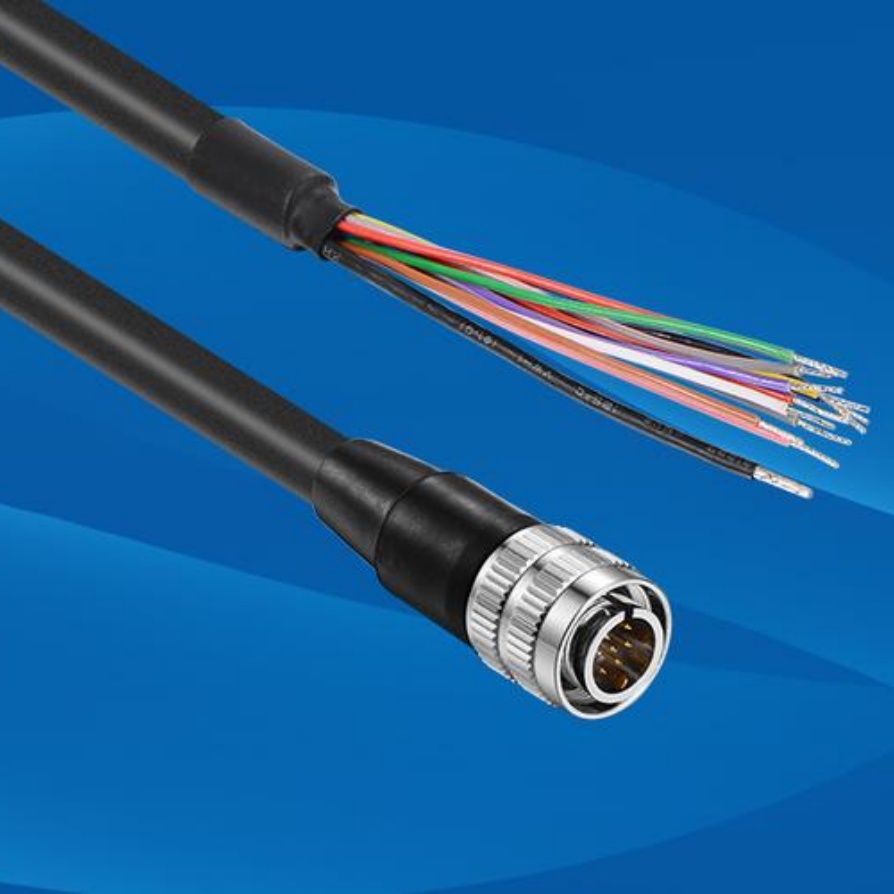
- Prepare the Cable End: Strip the outer jacket carefully without nicking inner conductors or shields. Expose the required length of conductors and shield.
- Prepare & Crimp Pins/Sockets: Strip each inner conductor precisely (length specified by the connector kit). Crimp each pin/socket onto the conductor using the correct die.
- Assemble the Connector: Insert the crimped pins into the new insert in the CORRECT ORDER (refer to wiring diagram/pinout – crucial!). Slide the insert into the shell, add seals/backshell/strain relief per kit instructions, ensuring the shield is properly terminated to the shell or designated grounding point inside the connector.
- Test Thoroughly: Before connecting to valuable equipment, retest continuity, shorts, and shield as in Step 2.
- Repairing a Cut Cable Section:
- Isolate the Damaged Section: Cut out the damaged portion cleanly.
- Prepare Both Ends: Strip back outer jacket and inner insulations on both sides to expose clean conductors and shield.
- Solder & Insulate (Wire-by-Wire):
- Twist & Solder: Twist matching conductors together tightly (e.g., wire 1 to wire 1, shield to shield). Apply solder smoothly. Avoid cold joints or excess solder.
- Insulate Individually: Slide heat-shrink tubing over each soldered joint before connecting the next wire. Seal each one individually with heat.
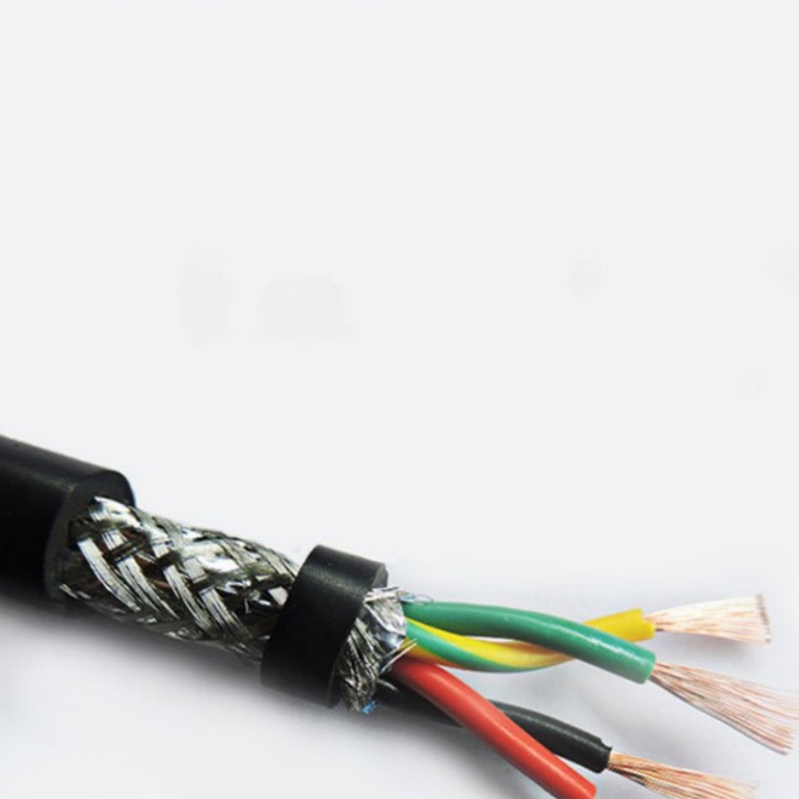
- Shield Repair: Splice the shield braid/foil by twisting strands together and soldering. Cover with a separate piece of heat shrink or conductive tape designed for shields.
- Seal the Repair: Use a high-quality, flexible self-fusing silicone tape (like Rescue Tape) or a section of large-diameter adhesive-lined heat shrink tubing over the entire repair section. This provides mechanical strength and environmental sealing.
- Test Thoroughly: As before. Note: This method adds stiffness and a potential failure point – use only if necessary.
- Minor Insulation Nick/Shield Damage:
- Clean the area thoroughly.
- Wrap damaged conductor insulation tightly with quality electrical tape.
- For shield damage:
- Separate and smooth braided shield strands.
- Apply conductive copper tape or shielding repair compound over the damaged section, ensuring contact with intact shield on both sides.
- Seal the entire area tightly with self-fusing silicone tape or adhesive-lined heat shrink.
Step 5: Preventing Future Damage
- Proper Strain Relief: Ensure cables are secured with appropriate strain relief clamps or boots within 6-12 inches of connectors.
- Routing & Protection: Use cable carriers (e.g., Igus chain), flexible conduit, or protective sleeving where exposed to abrasion, snagging, or crushing. Avoid tight bends exceeding cable spec. Secure cables loosely with ties – never over-tighten.
- Environmental Protection: Choose cables rated for the environment (oil-resistant, PUR jacket). Seal unused connector ports. Protect outdoor connections.
- Regular Inspections: Include cable inspection in routine maintenance checks. Look for wear points, stretching, and connector integrity.
Best Practices & Pro Tips
- Use OEM or Certified Connector Kits: Generic connectors often lead to intermittent faults or reduced bandwidth.
- Invest in the Right Tools: Precision crimpers with correct dies and good wire strippers are essential.
- Solder Quality Matters: Use a temperature-controlled iron with a fine tip and lead-free solder suitable for fine electronics.
- Label Everything: Document which wire goes to which pin before disassembly.
- Test Before Reintegration: Never assume the repair worked. Verify electrically first, then functionally with test equipment if possible.
- Know When to Call a Pro: For complex hybrid cables, high-speed data cables (CoaXPress, Camera Link), or situations exceeding your tools/comfort level, seek professional cable repair services or replace the cable.
- Maintain Spares: Critical cables should have verified spares on hand to minimize downtime.
Conclusion
Repairing damaged machine vision cables is a valuable skill that saves significant time and money but requires precision and the right approach. By carefully assessing the damage, using the correct components and tools, following meticulous procedures, and implementing robust strain relief and protection strategies, you can restore functionality reliably. Remember: safety is paramount, and sometimes replacement is the smarter business decision than repair. Prioritize prevention to keep your vision systems running smoothly.
(Word Count: Approx. 1250 | SEO Keywords: machine vision cable repair, damaged camera cable, replace M12 connector, GigE cable fix, industrial cable repair, continuity test, cable strain relief, data cable troubleshooting, CoaXPress repair, solder wire splice, cable shielding fix)


