How to Select Machine Vision Cables for High-Speed Applications: The ...
In the fast-paced world of automation and quality control, high-speed machine vision systems are essential. Cameras capturing thousands of frames per second generate massive data streams that must be transmitted flawlessly. The unsung hero enabling this critical data flow? Machine vision cables. Choosing the wrong cable can cripple system performance, leading to data loss, image corruption, and costly downtime. Selecting the right cable is paramount for success.
This guide dives deep into the critical factors for selecting machine vision cables optimized for high-bandwidth, high-speed applications, ensuring your vision system operates at peak efficiency and reliability.
Why Cable Selection is Critical for High-Speed Vision
High-speed cameras (GigE Vision, USB3 Vision, CoaXPress, Camera Link HS) push data rates into the gigabits or even tens of gigabits per second range. At these speeds, signal integrity becomes incredibly sensitive. Poor cable choice leads to:
- Signal Attenuation: Loss of signal strength over distance, degrading image quality.
- Jitter: Timing variations causing pixel errors and blurred images.
- EMI/RFI Interference: External noise corrupting the delicate image data signal.
- Reflections & Impedance Mismatches: Causing signal echoes and data errors.
- Data Packet Loss: Resulting in dropped frames or incomplete images.
- System Instability: Intermittent failures or complete communication loss.
Selecting cables designed explicitly for high-speed data transmission mitigates these risks.
Key Factors for Selecting High-Speed Machine Vision Cables
- Cable Type & Construction:
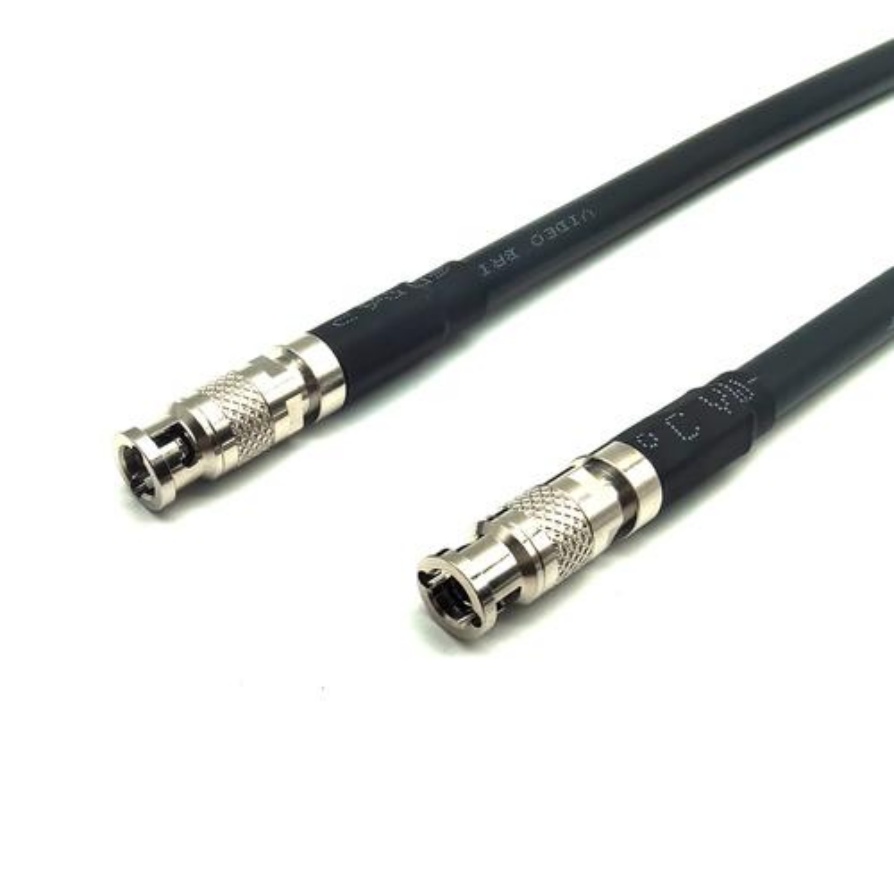
- Coaxial (Coax): Dominant for protocols like CoaXPress (CXP). Offers excellent high-frequency performance, inherent shielding, and good flexibility. Look for high-quality dielectric materials (e.g., low-density polyethylene – LDPE, or foam) for low signal loss and stable impedance.
- Twisted Pair (UTP/STP): Common for GigE Vision (Cat 5e/6/6a/7) and USB3 Vision. Twisting reduces EMI susceptibility. Shielded Twisted Pair (STP) or Screened Shielded Twisted Pair (S/STP) is highly recommended for industrial environments to combat EMI. Category ratings (Cat 6a, Cat 7) directly correlate with supported bandwidth and frequency.
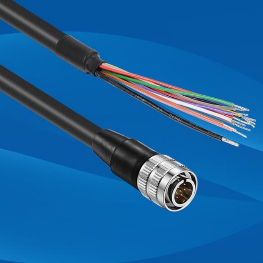
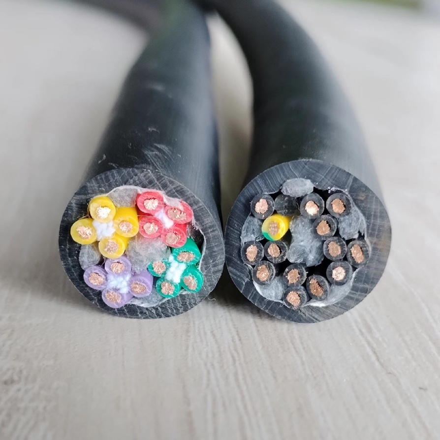
- Hybrid Cables: Combine power conductors (for power-over-camera standards like PoE, PoCL) with data pairs or coax in a single jacket. Ensure data and power sections are properly shielded from each other.
- Bandwidth & Data Rate Capability:
- Match the Cable to the Protocol: Ensure the cable’s rated bandwidth exceeds the maximum data rate required by your camera and protocol (e.g., CoaXPress 2.0 requires cables rated for 12.5 Gbps/lane, USB3 Vision Gen 1 needs 5 Gbps capability).
- Consider Future Needs: Opt for cables with headroom (e.g., Cat 6a for current GigE, even if Cat 5e technically suffices, to allow for upgrades).
- Length Matters: Signal attenuation increases with cable length. Higher data rates require shorter maximum cable lengths unless active components (repeaters, optical extenders) are used. Always consult the cable manufacturer’s specifications for maximum supported length at your target data rate.
- Shielding Effectiveness:
- Crucial for High-Speed Immunity: Industrial environments are electrically noisy (motors, drives, welders). Robust shielding is non-negotiable.
- Shielding Types:
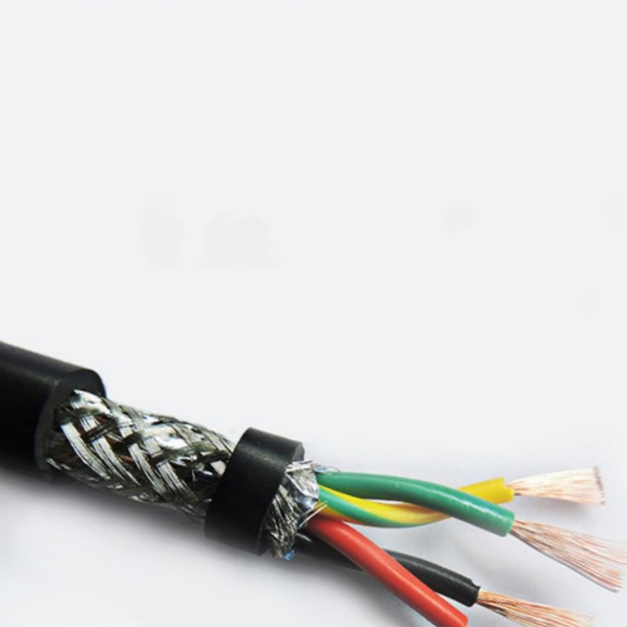
- Foil Shields: (e.g., Aluminum/Polyester Tape) Provide 100% coverage against high-frequency interference. Essential for data lines.
- Braided Shields: (e.g., Tinned Copper Braid) Offer excellent low-frequency EMI protection and high flex life. Often used over foil or as the primary shield.
- Combination Shields: Foil + Braid shields offer the best overall protection (e.g., S/STP for Ethernet). Look for high coverage percentages (≥85% braid coverage is good, ≥95% is excellent).
- Overall Cable Shield: Hybrid cables need an overall shield encompassing all internal components.
- Connectors:
- Precision & Quality: High-speed connectors must maintain consistent impedance and provide excellent shielding continuity. Cheap connectors are a major point of failure.
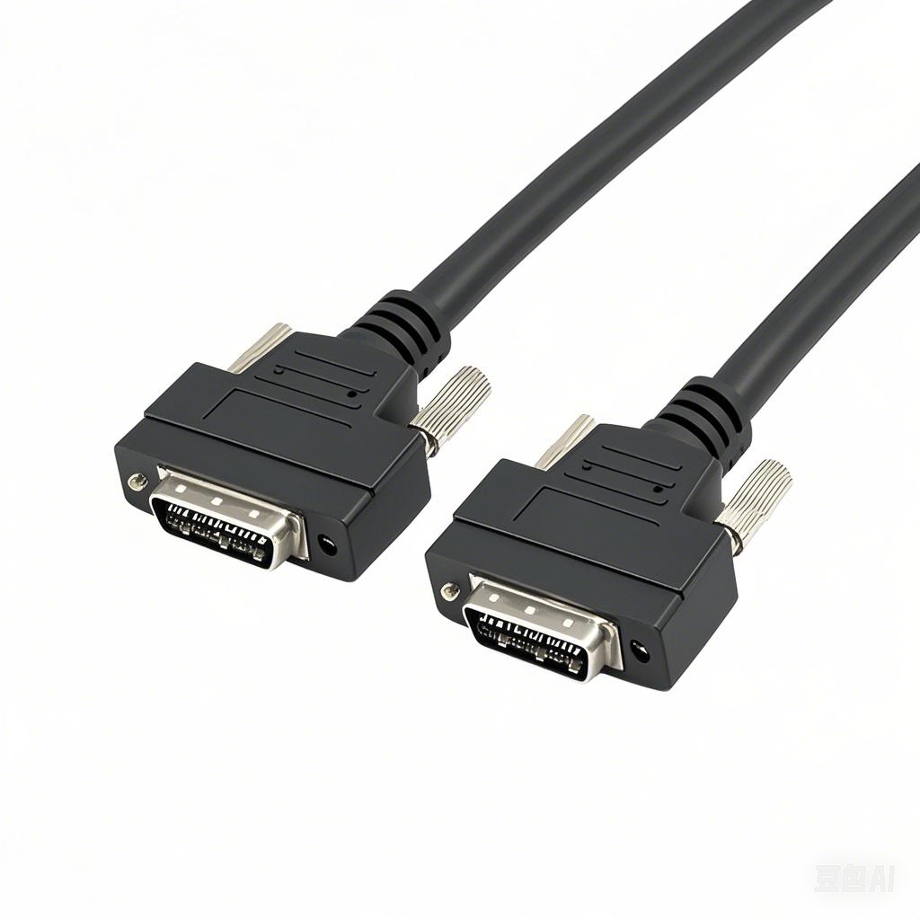
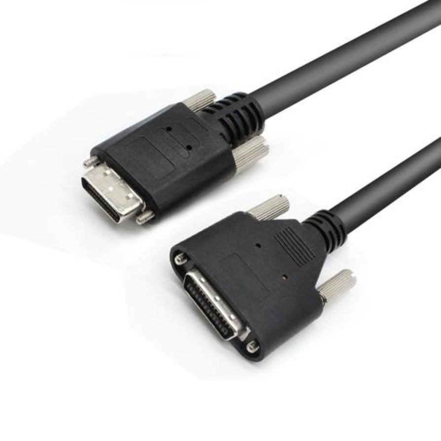
- Protocol Specificity: Use connectors specified for the protocol (e.g., BNC or DIN 1.0/2.3 for Coax/CXP, RJ45 for GigE, USB Type B or Micro-B for USB3 Vision, MDR for Camera Link HS).
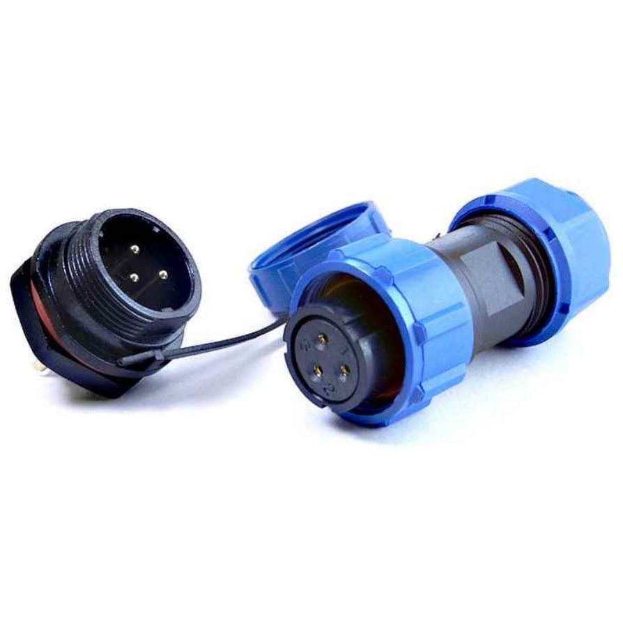
- Locking Mechanisms: Secure connections prevent accidental disconnection due to vibration (common in factories). Screw locks (BNC), latch locks (RJ45), or positive locking mechanisms (MDR) are vital.
- Shield Termination: Ensure connectors provide a 360-degree termination point for the cable shield to maintain EMI integrity.
- Flexibility & Durability:
- Flex Life Rating: How many bend cycles can the cable withstand before failure? High-flex cables (often using finely stranded conductors and specialized jacketing) are essential for robots, moving arms, or cable carriers (e.g., IGUS Chain). Look for ratings like 5 million+ cycles.
- Jacket Material: Needs to be durable, resistant to oils, chemicals, abrasion, and often flexible. Common materials include PVC (general purpose), PUR (excellent oil/flex resistance), and TPEs (wide temperature/chemical range).
- Strain Relief: Integrated or added strain relief at connector ends prevents conductor breakage from repeated bending or pulling.
- Impedance Matching:
- Critical for Signal Integrity: The cable’s characteristic impedance must match the source (camera) and load (frame grabber/PC) impedance. Mismatches cause signal reflections.
- Standard Values: Coax is typically 75 Ohms (video) or 50 Ohms (some data). Twisted pair Ethernet is 100 Ohms. USB is 90 Ohms differential. Ensure consistency throughout the signal path.
- Compliance with Standards:
- Protocol Standards: Ensure cables meet or exceed the requirements of the relevant vision standard (GigE Vision, USB3 Vision, CoaXPress, Camera Link HS).
- Industry Standards: Look for certifications like UL, CE, RoHS. Compliance with ISO, IEEE (for Ethernet), or IEC standards indicates rigorous testing.
Best Practices for Installation & Maintenance
- Avoid Sharp Bends: Respect the cable’s minimum bend radius, especially during installation and in cable carriers.
- Secure Cabling: Use clamps, ties, or carriers to prevent strain on connectors and minimize movement-induced wear. Avoid tension.
- Separate Power & Data: Route high-power cables away from vision data cables whenever possible. Cross them at right angles if necessary.
- Grounding: Ensure proper grounding of equipment and cable shields according to the camera and frame grabber manufacturer’s instructions.
- Inspect Regularly: Check cables for signs of wear, kinking, crushing, or damage to the jacket and connectors. Replace damaged cables immediately.
Conclusion: Invest in Quality for Reliable High-Speed Vision
Selecting machine vision cables for high-speed applications is not a place to cut corners. The cost of cable failure – in terms of downtime, scrap, and missed inspections – far outweighs the price premium for high-quality, purpose-built cables.
By carefully considering cable type, bandwidth, shielding, connectors, flexibility, impedance, and standards compliance, you ensure your high-speed vision system delivers the consistent, reliable, and high-fidelity image data required for demanding automation tasks. Partner with reputable cable manufacturers who specialize in industrial machine vision solutions and can provide detailed specifications and application support. Investing in the right cable infrastructure is fundamental to unlocking the full potential of your high-speed machine vision investment.


