How to Test a Machine Cable for Faults
Machine cables are critical components in industrial equipment, transmitting power and signals to ensure smooth operation. Over time, wear, environmental damage, or manufacturing defects can lead to faults that disrupt performance or even pose safety risks. Testing these cables systematically helps identify issues early, preventing costly downtime. Below is a step-by-step guide to effectively testing machine cables for faults.
1. Safety First: Prepare for Testing
Before starting any tests, prioritize safety:
- Disconnect Power: Ensure the cable is fully disconnected from all power sources and equipment to avoid electric shock.
- Check Environmental Conditions: Test in a dry, clean area. Moisture or debris can interfere with readings or cause accidents.
- Use Protective Gear: Wear insulated gloves, safety glasses, and appropriate footwear to minimize risks.
2. Visual Inspection: Spot Obvious Issues
A thorough visual check can reveal many common faults:
- Physical Damage: Look for cuts, abrasions, or kinks in the cable jacket, which may expose internal conductors to moisture or corrosion.
- Burning or Discoloration: Darkened areas or a burnt smell indicate overheating, often caused by excessive current or poor connections.
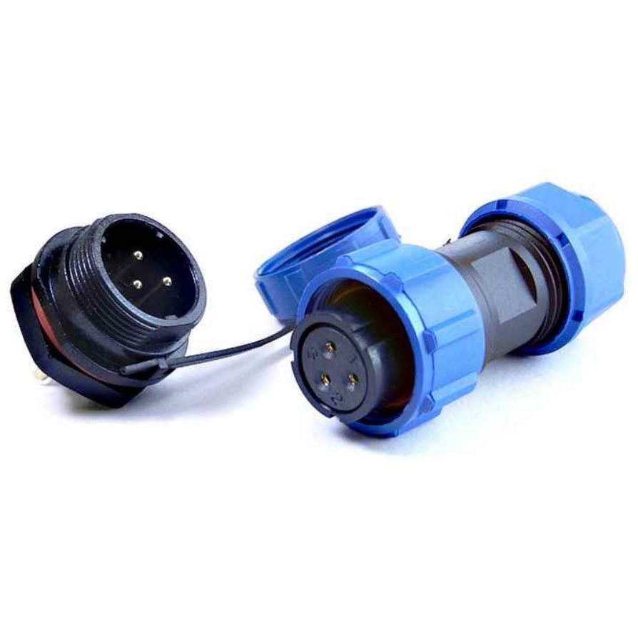
- Connector Problems: Check for bent pins, loose terminals, or corrosion on connectors—these can cause intermittent or total failure.
- Crushing or Pinching: Inspect areas where the cable passes through tight spaces or is in contact with moving parts, as these can damage internal wires.
3. Basic Continuity Testing: Identify Breaks
Continuity testing checks if electrical current can flow through the cable, identifying 断路 (open circuits):
- Tools Needed: A multimeter set to the continuity mode (usually marked with a sound wave icon).
- Procedure:
- Disconnect the cable from all devices.
- Touch one probe of the multimeter to one end of a conductor (e.g., a wire in the cable).
- Touch the other probe to the corresponding end of the same conductor on the opposite side of the cable.
- A audible beep or a reading close to 0 ohms indicates continuity (no break). No beep or a high resistance reading (e.g., 1MΩ or more) means there’s a break in the conductor.
- Note: Test each conductor individually, labeling them if necessary to avoid confusion.
4. Insulation Resistance Testing: Detect Leaks
Insulation resistance testing measures how well the cable’s insulation resists current leakage, identifying insulation breakdown (a common cause of shorts or ground faults):
- Tools Needed: A megohmmeter (megger), which applies high voltage (typically 500V or 1000V) to test insulation.
- Procedure:
- Ensure the cable is disconnected and clean.
- Connect one lead of the megger to a conductor.
- Connect the other lead to the cable’s jacket (ground) or another conductor (to test for cross-insulation).
- Apply voltage as per the megger’s instructions and record the resistance reading.
- Interpret Results:
- New cables should show resistance above 100MΩ.
- Readings below 1MΩ indicate significant insulation damage, requiring repair or replacement.
- A sudden drop in resistance during testing suggests a partial breakdown that may worsen over time.
5. Short Circuit Testing: Find Unwanted Connections
Short circuits occur when two conductors touch, causing excessive current. To test for shorts:
- Tools Needed: Multimeter (resistance mode) or megohmmeter.
- Procedure:
- Disconnect the cable and separate all conductors.
- Set the multimeter to resistance mode (ohms).
- Touch one probe to one conductor and the other probe to a different conductor.
- A reading of 0 ohms (or very low resistance) indicates a short between the two conductors. A high resistance reading (e.g., 10MΩ or more) means no short.
6. Advanced Testing for Complex Faults
For intermittent or hard-to-detect faults, use specialized tools:
- Time Domain Reflectometer (TDR): Sends a signal through the cable and analyzes reflections to pinpoint the location of breaks or shorts (useful for long cables).
- Thermal Imaging Cameras: Detect overheating areas, which often indicate high resistance connections or internal damage.
- High-Potential (Hi-Pot) Testers: Apply extreme voltage to stress insulation, revealing hidden weaknesses that standard tests might miss (use with caution and only on appropriate cables).
7. Post-Test Actions
After identifying a fault:
- Locate the Exact Point: For breaks or shorts found via TDR, mark the cable at the calculated distance and inspect that area for physical damage.
- Repair or Replace: Small insulation damage can sometimes be repaired with heat-shrink sleeves, but severe damage or conductor breaks usually require replacing the cable.
- Retest: After repair or replacement, repeat tests to confirm the fault is resolved.
By following these steps, you can systematically diagnose faults in machine cables, ensuring reliable performance and reducing the risk of unexpected failures. Regular testing, combined with proper cable handling and maintenance, extends cable life and keeps equipment running efficiently.


