How to Troubleshoot Common Machine Vision Cable Problems
Machine vision systems are powerful tools, but they rely heavily on reliable connections. When image quality degrades, cameras drop out, or systems freeze, faulty cables are frequent culprits. Diagnosing cable issues quickly minimizes costly downtime. Here’s a practical guide to troubleshooting the most common machine vision cable problems:
1. Start with the Basics: Visual & Physical Inspection (The Quick Wins)
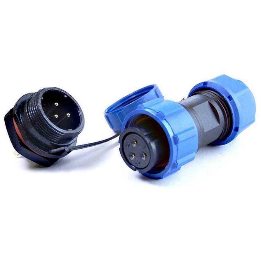
- Check Connections: Are all cable connectors fully seated and locked (especially M12/X-coded, RJ45)? Are mating connectors clean? Power off the system before unplugging/replugging.
- Look for Damage: Examine the entire cable length for:
- Obvious Breaks/Kinks: Sharp bends, cuts, crushing from pinch points or heavy objects.
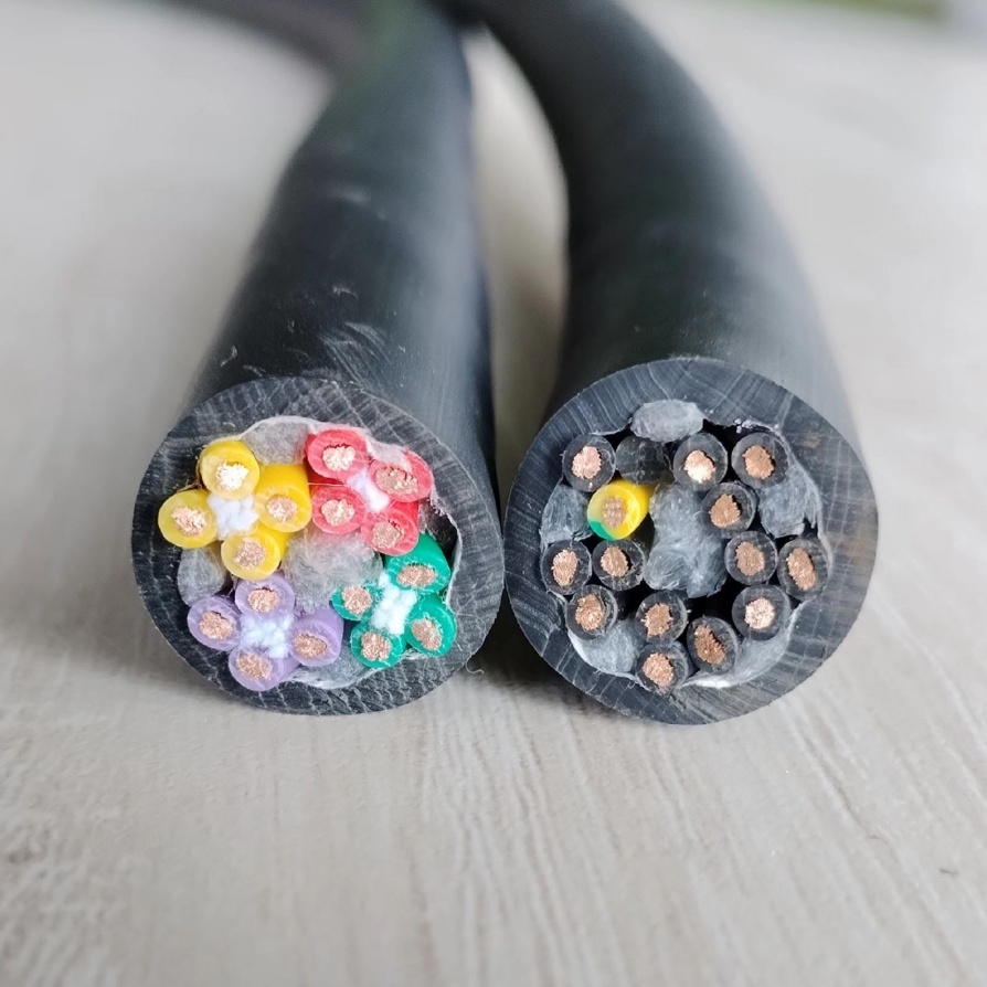
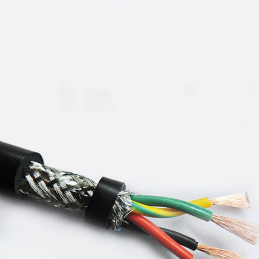
- Shielding Damage: Fraying metal braid or foil visible near connectors or damage points.
- Connector Pins: Bent, pushed-back, corroded, or contaminated pins.
- Strain Relief: Ensure cables aren’t putting direct strain on connector solder joints. Use clips or strain relief brackets.
- Movement Checks: Wiggle the cable gently near connectors and along its run while observing the camera feed or system status. Intermittent faults often show up here.
2. Dealing with Intermittent Signals & Dropouts
- Wiggle Test Confirmation: If wiggling the cable causes flickering, black screens, or errors, isolate the section. Wiggle near connectors first, then along bends. Mark the spot.
- Connector Corrosion/Contamination: Especially in harsh environments (coolant, dust). Solution:
- Clean: Use compressed air (dry only!) to blow out connectors. For delicate contacts, consider isopropyl alcohol (99%) and a lint-free swab – power off completely first.
- Protect: Use appropriate connector caps when unplugged. Consider protective boots or conduits.
- Loose Connectors/Locks: Ensure locking mechanisms (threads, clips) are fully engaged. Replace damaged connector boots.
- Internal Wire Break: Microscopic breaks inside the insulation, often at stress points, cause intermittent faults. A cable tester helps identify which wire is affected. Replace the cable.
3. Combating EMI/RFI Noise (Electrical Interference)
- Symptoms: “Sparkly” image noise, rolling bars, erratic behavior, CRC/packet errors (GigE), signal dropout.
- Troubleshooting:
- Separation: Is the vision cable running parallel to high-power cables (motors, drives, welding)? Separate them by at least 12 inches (30cm) or cross them at 90-degree angles.
- Shielding: Verify cable has metallic foil/braid shield. Ensure shield is properly connected and grounded at one end only (usually the controller/PC side) via the connector housing. Damaged shielding drastically reduces effectiveness.
- Grounding: Check system grounding points. Poor grounding can make equipment more susceptible to noise. Ensure equipment chassis are grounded.
- Route: Avoid running vision cables near VFDs, large motors, or RF sources whenever possible. Use shielded conduits if necessary.
- Solution: Improve cable routing, repair/replace damaged shielded cables, use ferrite chokes on both ends if needed.
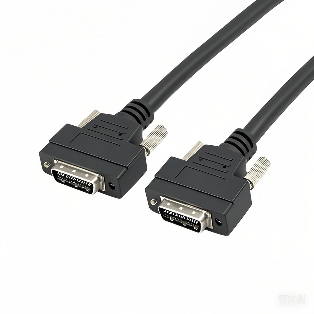
4. Ensuring Signal Integrity & Data Throughput (GigE, CoaxPress, USB3, Camera Link)
- Symptoms: Low frame rates, image lag, dropped frames, CRC errors, unstable high-resolution images.
- Troubleshooting:
- Cable Length: Exceeding the maximum rated length for the protocol degrades signal significantly. Refer to cable specs and protocol standards (e.g., GigE often maxes at 100m w/ good Cat6). Use repeaters/fiber optic extenders for longer runs.
- Cable Category/Quality: Using sub-standard cables (e.g., Cat5e for demanding GigE Vision instead of Cat6A) causes issues. Ensure certified cables matching your protocol’s requirements.
- Connectors & Terminations: Poorly crimped RJ45 jacks or damaged coaxial connectors cause reflections and signal loss.
- Bandwidth: For digital protocols, ensure the cable’s bandwidth rating meets the required camera data rate.
- Solution: Verify cable lengths, use protocol-specific certified cables, replace faulty terminations or connectors.
5. Verifying Wiring & Pinouts (Power, IO, Serial)
- Symptoms: Camera doesn’t power on, strobe lights not triggering, PLC inputs not registering, serial communication failure.
- Troubleshooting:
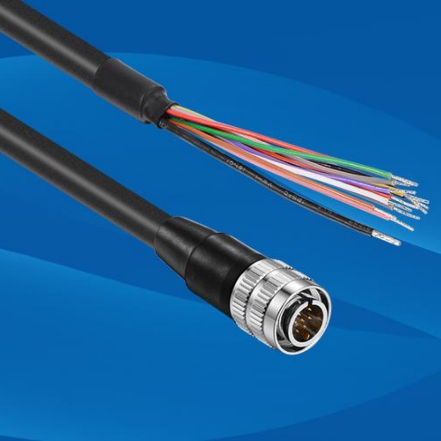
- Multimeter Test: (Power OFF) Check continuity between pins at each end. Ensure no shorts between pins (+Ve to GND) or open circuits (broken wire).
- Pinout Diagram: Crucially, have the correct pinout diagram for BOTH ends of the cable and the devices (camera, power supply, PLC card, controller). Mismatched custom cables are a common source of errors.
- Power Levels: Verify correct voltage reaches the camera connector pins.
- Solution: Correctly re-wire connectors using verified pinout diagrams. Replace the cable if internal wiring is wrong or damaged.
Troubleshooting Workflow Summary
- Observe Symptoms: What exactly is failing? (Image? Power? Comm?)
- Power Down & Visual Inspection: Look, feel, wiggle.
- Simplify: If possible, test the camera with a known-good, short cable on the bench.
- Swap (Known Good Cable): The quickest test. Replace suspect cable.
- Check EMI/RFI Environment: Routing, shielding, grounding.
- Use Tools:
- Multimeter: Continuity, shorts, voltage.
- Cable Tester: Identify broken wires, shorts, miswires (especially complex harnesses).
- Network Sniffer/Software Tools: Diagnose packet drops, CRC errors (GigE).
- Consult Documentation: Pinouts, protocol specs, cable specs.
When in Doubt (or for Intermittent Faults):
- Replace the Cable: Often the most time-effective solution after basic checks. Keep spares of critical cables onsite.
- Seek Professional Help: For complex installations, signal integrity analysis, or persistent EMI issues, consulting the system integrator or protocol specialists may be necessary.
By systematically checking these common failure points, you can quickly identify and resolve machine vision cable problems, ensuring your vision systems stay online and delivering reliable results. Remember: Start simple, look for damage, isolate the problem, and rule out interference.


