How to Verify Machine Vision Cable Specifications
Choosing the right machine vision cable is critical for system performance and reliability, especially in demanding industrial environments. Cable datasheets provide key specifications, but how can you be confident these claims are accurate and relevant to your application? Relying solely on manufacturer claims can lead to unexpected failures. Here’s how to effectively verify machine vision cable specifications:
1. Go Beyond the Datasheet: Scrutinize Documentation & Support
- Request Detailed Test Reports: Don’t settle for generic “complies with…” statements. Ask the manufacturer or distributor for specific test reports (like IEC, UL, IEEE, or internal) related to the claimed specifications. For example:
- Flex Life: Ask for the test report showing the bend radius, test method (e.g., CC6 chain per IEC 61076-2-101), cycle count achieved, and pass/fail criteria used. Was the test done at room temperature or elevated temperature? How was failure defined (e.g., electrical continuity drop, visible damage)?
- EMI Performance: Request shielding effectiveness (attenuation) graphs measured per relevant standards (e.g., IEC 61196-1), showing performance across the required frequency range.
- Temperature Rating: Ask for UL/CSA/IEC certification numbers specifically for that cable type, not just generic polymer ratings. Verify the test duration and conditions.
- Demand Real Data Sheets: Ensure the datasheet corresponds exactly to the specific part number you intend to purchase. Generic or “typical” datasheets lack the necessary detail for verification.
- Ask Application-Specific Questions: Provide your specific details (cable length, required bend radius, expected cycles per day, environmental factors like oils/chemicals, required connector types) to the manufacturer/supplier tech support. Ask pointedly: “Based on the actual test data for this specific cable, can it reliably perform under *these exact conditions?“*
- Verify Certifications: Check claimed certifications (UL, CE, RoHS, REACH, specific flame ratings like UL AWM/IEC) on the relevant certification body databases using the unique file number or product identifier.
2. Conduct Your Own Physical Inspection & Simple Tests
- Examine Construction Samples: Obtain samples (if possible) before bulk ordering.
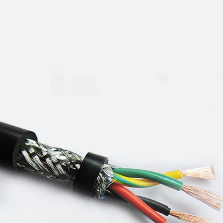
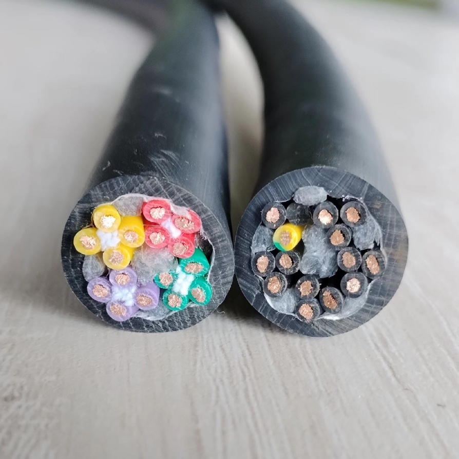
- Conductor Stranding: Cut a short length and strip back the jacket/shield. Use a magnifying glass or microscope to inspect the conductor stranding. Verify fine-stranding for flex applications. Coarse strands break faster.
- Shielding: Visually inspect the shielding. Is it a foil only (rarely sufficient for vision)? Braid only? Foil plus braid (ideal)? Measure the braid coverage – tight weave with >85% coverage is a good sign. Look for foil coverage consistency.
- Jacket Material: Check markings and compare to datasheet claims. Assess flexibility by hand – PUR jackets should feel significantly more supple than standard PVC. Does the surface feel smooth? Check for oil resistance if claimed.
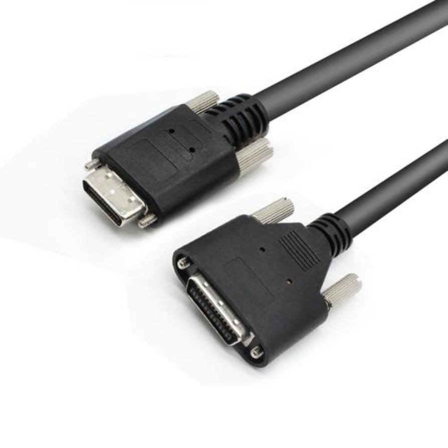
- Connector Inspection: Examine the connector strain relief. Is it a robust, overmolded boot? How securely does it capture the cable jacket? Inspect the solder joints/crimps inside if possible (requires disassembly). Quality termination is crucial.
- Flexibility Assessment (Subjective but Indicative): Gently bend the sample tightly. Does it kink easily? Does the jacket feel like it might crack? Does it spring back to shape? A poor “hand feel” often indicates inflexibility.
- Continuity & Resistance Test: Use a multimeter to check core-to-core continuity and measure conductor resistance per meter. Compare against datasheet values. Higher than expected resistance can indicate undersized conductors or poor stranding.
3. Prioritize Functional Testing (Simulate Your Application)
This is the gold standard for verification, especially for critical or demanding applications.
- Build a Flex Test Rig: Create a setup that closely mimics your real-world cable motion.
- For drag chains, mount the cable in a chain with the required bend radius and run it continuously.
- For robot arms or torsional stress, replicate the range of motion.
- Monitor Electrical Performance: Don’t just wait for complete failure. Continuously monitor during the test:
- Signal Integrity: Use a network tester, Bit Error Rate Tester (BERT), or visually monitor the camera image stream/Data Matrix code reading reliability for noise, dropouts, or artifacts.
- Continuity & Resistance: Periodically interrupt the flex test to measure core resistance. A gradual increase signals conductor fatigue. Intermittent shorts indicate shield or insulation failure.
- Track Flex Cycles: Precisely count the number of bending/twisting cycles applied.
- Apply Environmental Stress: If applicable, expose the test setup to the expected temperatures, oils, coolants, or cleaning chemicals.
- Record & Document: Note when signal degradation starts, when resistance exceeds acceptable limits, and when complete failure occurs. Document observations like kinking, jacket cracking, or shield protrusion.
- Compare to Claimed Flex Life: Your actual test results (cycles to degradation/failure) under your specific conditions are the ultimate verification tool against the manufacturer’s claims generated under potentially different lab conditions.
4. Leverage Independent Labs & Trusted Reviews
- Third-Party Testing: For the highest confidence, especially for large projects or critical systems, send samples to an independent testing lab specializing in cables. Request testing against the most critical specifications for your application using recognized methods (e.g., IEC standards).
- Industry Reputation & References: Research the manufacturer’s reputation among machine vision integrators and OEMs. Talk to colleagues or industry forums about real-world experiences with specific cable brands/part numbers for similar applications.
Key Specifications to Verify Meticulously
- Flex Life / Bending Cycles: The number one culprit for premature failure.
- Minimum Bending Radius: Must be achievable in your specific pathway/carrier.
- Conductor Gauge & Resistance: Impacts voltage drop and power delivery.
- Shielding Effectiveness (dB): Critical for EMI resistance and signal integrity.
- Bandwidth / Data Rate: Does it support your camera’s protocol and resolution?
- Jacket Material & Properties: (Oil resistance, chemical resistance, temperature rating, flame retardancy, abrasion resistance).
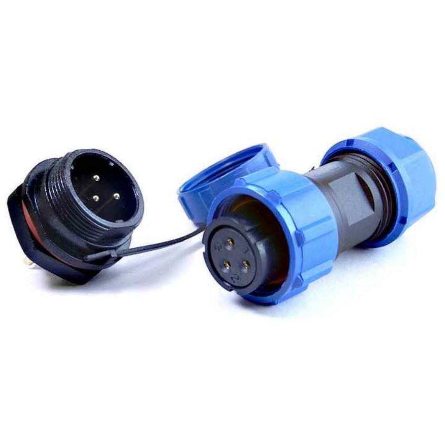
- Connector Type & Locking Mechanism: Correct mating interface and secure connection.
Conclusion
Verifying machine vision cable specifications isn’t just about reading a datasheet; it’s an active process of scrutiny, questioning, and practical testing. By demanding detailed test reports, physically inspecting samples, conducting application-specific functional testing, and utilizing independent resources, you gain the confidence needed to select cables that will deliver reliable, high-performance operation over the long haul. Investing time in verification upfront prevents costly downtime, troubleshooting headaches, and system failures later. Don’t gamble on unverified claims – test, inspect, and verify.


