Machine Vision Cable Grounding Problems: Quick Troubleshooting Guide
Machine vision systems are the eyes of modern automation, demanding flawless image acquisition. Yet, elusive problems like flickering images, streaks, distorted pixels, or complete signal dropout can grind production to a halt. Often, the silent culprit lies not in the camera or software, but in improper cable grounding. Solving grounding issues is critical for system stability. This guide cuts through the complexity, offering actionable steps to quickly diagnose and resolve common machine vision cable grounding problems.
Recognizing the Symptoms of Grounding Issues
Before diving in, confirm your problem smells like grounding/EMI:
- Intermittent Glitches: Image flickering, random noise spikes, temporary signal drops, or sudden communication errors.
- Structured Noise: Repeating patterns (stripes, waves), consistent dark/light bands, or distortion across the image.
- Signal Dropout/Freezes: Camera losing connection to the frame grabber/controller.
- Erratic Behavior: Unexplained communication errors, camera resets, or inconsistent triggering.
- Physical Issues: Humming/buzzing sounds near cables or connectors (sometimes audible), or even noticeable heat on cable shields.
Quick Troubleshooting Steps (The 15-Minute Fix Rush)
Focus on these fast checks and simple solutions first:
- The Power Cycle & Re-seat: Start simple. Power down everything (camera, controller, lights, PLC). Disconnect and reconnect all vision cables (power, data, I/O). Ensure connectors click firmly into place. Power back up sequentially. This fixes poor connections, the #1 easy win.
- Isolate the Suspect Cable Chain: Disconnect non-essential devices temporarily. Does the problem disappear? Reconnect one by one to identify the offending component or cable.
- Check Shield Termination – The Usual Suspect: This is ground zero for grounding problems.
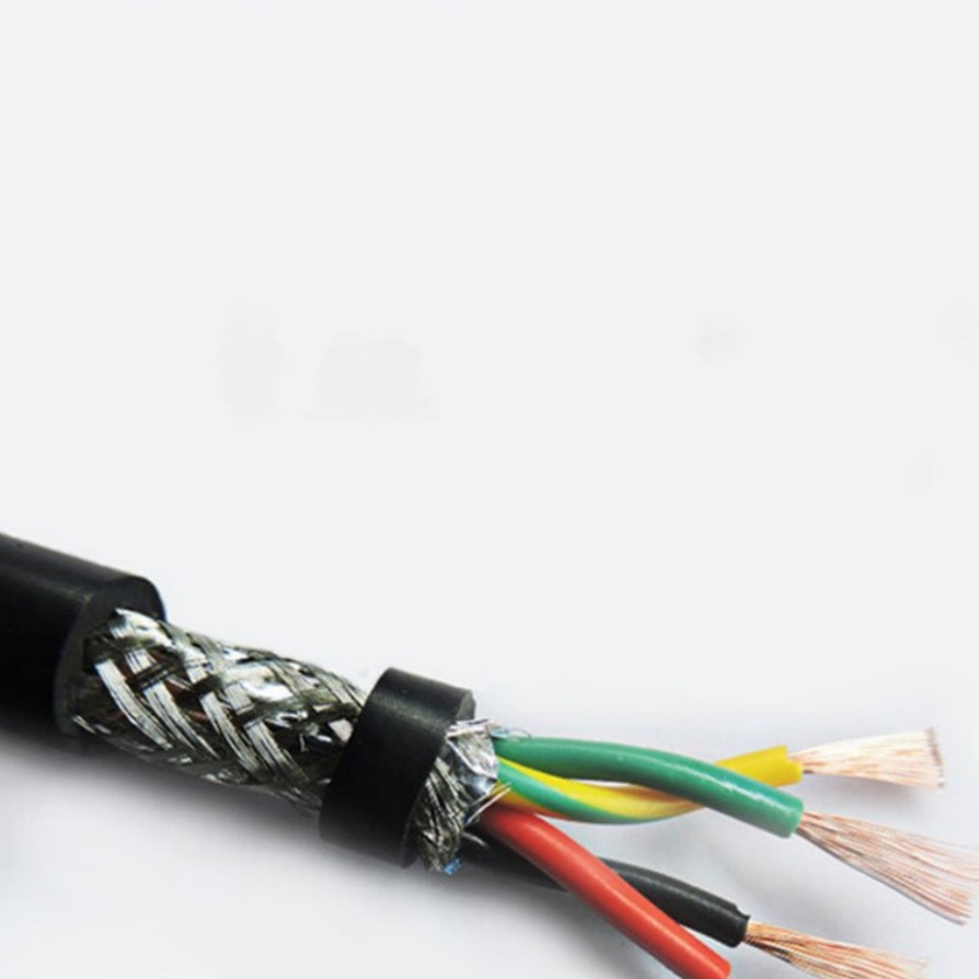
- End-to-End Shield Path: Verify the cable’s braided or foil shield is securely connected at BOTH ENDS – camera connector housing AND frame grabber/controller connector housing.
- Chassis Grounding: Ensure these connector housings are making solid electrical contact with the metal chassis of their respective devices (no paint or anodizing insulation!). Tighten D-shell screws securely.
- Dongles/Adapters: If used, confirm they are properly shielded and grounded too.
- **”Pigtail” Peril:** Look for the dreaded “pigtail” – where the shield is gathered into a wire and connected to a ground point on a circuit board. This is highly problematic at high frequencies. Prefer 360-degree clamp connections to chassis metal whenever possible.
- Inspect for Physical Damage: Look for:
- Pinched, crushed, or kinked cables.
- Cuts or abrasions in outer jacket potentially exposing shielding.
- Bent or damaged connector pins (power, data, ground).
- Corrosion on connectors or shield contacts.
- Ground Loop Suspicions: Symptoms often appear after adding/changing equipment.
- Try Single-Point Ground: Temporarily lift (disconnect) the shield connection at only one end of the camera cable (typically the controller/frame grabber end, but consult manuals). Never float both ends! If the noise/issue vanishes or significantly reduces, you likely have a ground loop. A permanent solution requires resolving the voltage difference (next section).
Deeper Dive: Solutions for Persistent Grounding Issues
If the quick fixes haven’t resolved it, dig deeper:
- Confirm Overall Power and Earth Ground: Use a multimeter:
- Check continuity between the earth ground pin of the main system power supply plug and a known good earth ground point (like a building steel beam ground lug).
- Verify AC voltage between power supply DC outputs (e.g., 24V+) and earth ground is stable and as expected. Significant AC ripple indicates a failing power supply introducing noise.
- Fighting Ground Loops (Identified from Step 5):
- Maintain the Shield Lift: If lifting one shield end worked, make it permanent using an isolating connector (like GigE Vision with transformer-isolated RJ45 ports, or industrial Ethernet switches with DC-bias blocking) OR use a video isolation transformer (for analog cameras like Camera Link).
- Address Root Cause: The ideal solution is eliminating the voltage difference between chassis grounds. Ensure all equipment racks/cabinets are bonded to the same low-impedance earth ground point using heavy-gauge wire or braids (“equipotential bonding”). Verify PLCs, VFDs, large motors, and vision equipment share this common ground.
- Improve Shield Effectiveness:
- Replace “Pigtails”: If your system uses shield pigtails soldered to a PCB ground and you suspect it’s inadequate, replace it with a proper clamp-style connector providing a full 360-degree shield connection to the chassis.
- Ground Cable Entry Plate: Use metal gland plates or connectors where cables enter enclosures, bonding the cable shield to the plate immediately upon entry.
- Manage High-Frequency EMI: For RF noise sources (VFDs, welding, radio transmitters):
- Shield Gaps: Ensure no gaps in shielding coverage. Use fully shielded cables end-to-end (Power-over-Ethernet cameras need shielded ethernet!).
- Ferrite Cores: Snap ferrite cores (chokes) onto suspect cables close to the equipment entry point. Try multiple turns if needed. This suppresses high-frequency noise radiating on the cable.
- Increase Distance: Physically separate vision cables from power cables (especially motor leads) and known noise sources by as much distance as possible (ideally 12+ inches). Route perpendicularly if crossing.
- Metal Conduit: Running shielded cables through grounded metal conduit provides extra shielding effectiveness.
Prevention is Cheaper Than Downtime
- Specify & Inspect Cables: Use high-quality, double-shielded cables designed specifically for industrial machine vision applications and data rates (e.g., GigE Vision Cat6a SF/UTP, MDR Camera Link). Inspect new cables before installation.
- Chassis Grounding is Paramount: Design your electrical panels and equipment mounting so all metal enclosures connect securely to earth ground.
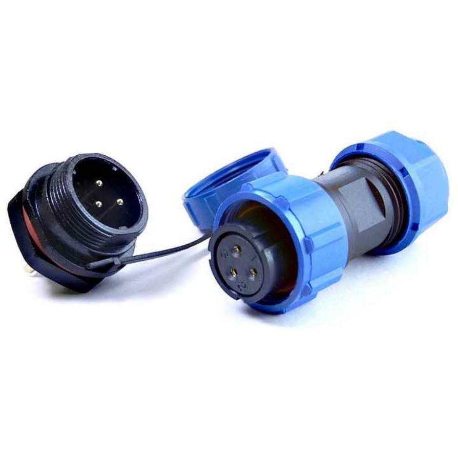
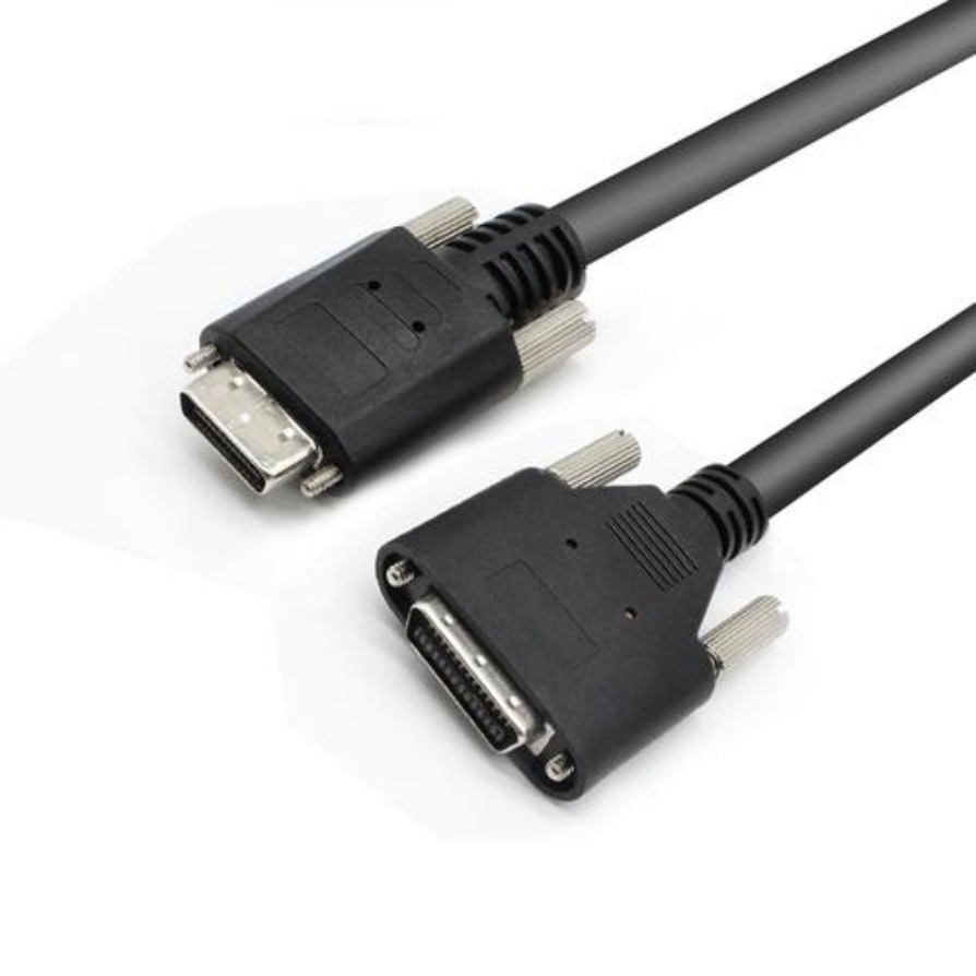
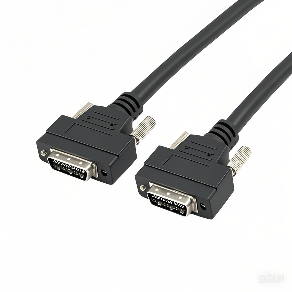
- Connector Choice Matters: Opt for connectors with robust, metal-shell shielding designed for direct chassis connection. Avoid plastic-bodied connectors where shielding is critical.
- Strategic Isolation: Plan for isolated signals (using opto-isolators, transformer-coupled Ethernet, isolators) at the boundaries between different equipment grounds or noisy environments.
When to Call the Experts
If you’ve systematically tried these steps and the problem persists:
- Check Manufacturer Docs: Specific devices (Cognex cameras, Basler cameras, Keyence systems) often have detailed grounding recommendations in their installation guides. Consult them!
- Suspect Component Failure: The problem could be a failing camera sensor, power supply, or frame grabber generating noise internally. Try swapping components if possible.
- Complex Environments: Extremely noisy environments (heavy welding, large plasma systems) require specialized EMI mitigation strategies.
Conclusion
Machine vision cable grounding problems manifest in frustratingly vague ways but often have specific solutions. By methodically checking shield termination, diagnosing ground loops, improving grounding paths, and managing EMI, you can swiftly restore image integrity and system reliability. Bookmark this guide – mastering grounding fundamentals saves significant time and prevents costly downtime in your automated processes. Remember: a clean ground equals a clear image!


