Understanding Impedance in Coaxial Machine Vision Cables: A Guide to ...
In machine vision systems, every component plays a critical role in ensuring accuracy, speed, and reliability. While cameras, lenses, and software often steal the spotlight, coaxial cables are the unsung heroes that transmit high-frequency signals between cameras, sensors, and processors. A key factor influencing their performance is impedance—a concept that, if misunderstood, can lead to signal degradation, data loss, and system failures. This article explains what impedance means in coaxial machine vision cables, why it matters, and how to choose the right cable for your application.
What Is Characteristic Impedance in Coaxial Cables?
Characteristic impedance (measured in ohms, Ω) is a fundamental property of coaxial cables that determines how electrical signals propagate through them. Unlike resistance, which applies to direct current (DC), impedance accounts for alternating current (AC) behavior, including capacitance and inductance effects.
In coaxial cables, impedance is determined by:
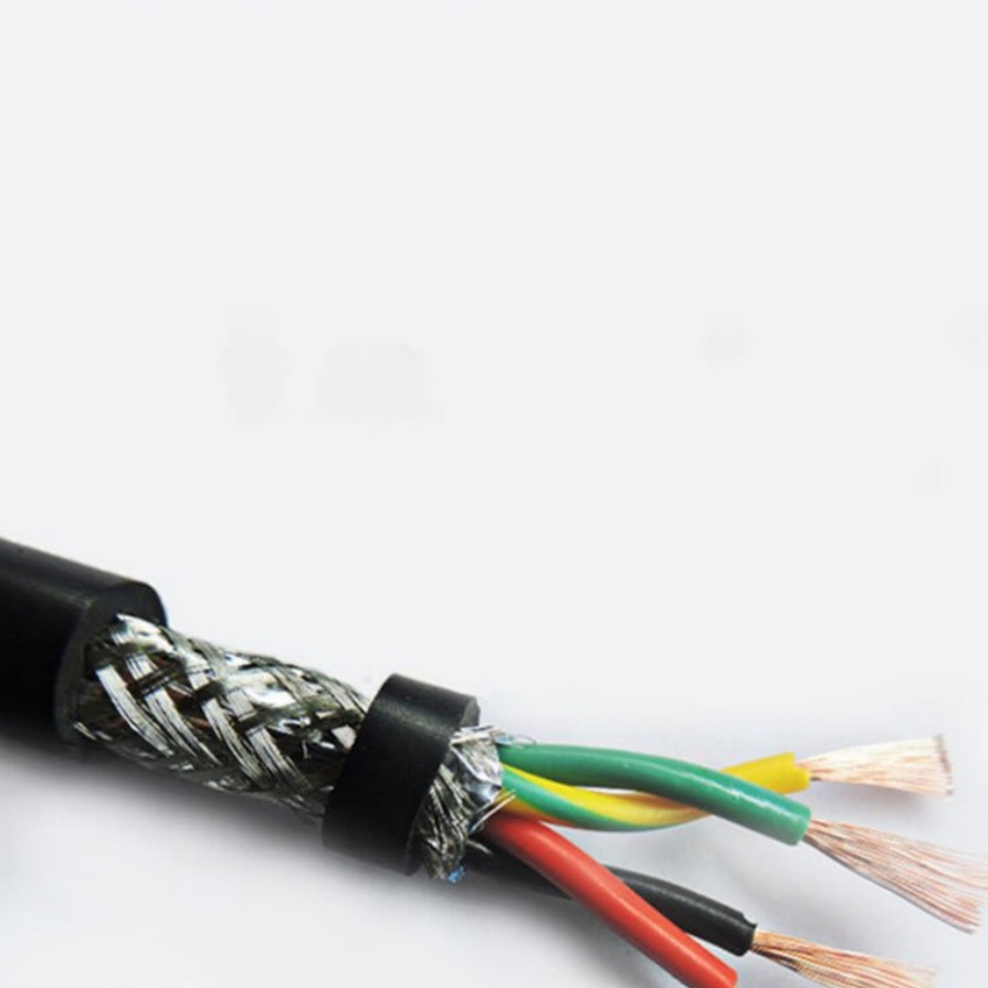
- Physical dimensions: The ratio of the inner conductor’s diameter to the outer shield’s diameter.
- Dielectric material: The insulating material between the conductors (e.g., polyethylene, foam).
Most machine vision systems use cables with 50 Ω or 75 Ω impedance, standardized to ensure compatibility across devices.
Why Impedance Matters in Machine Vision Systems
- Signal Integrity
High-speed machine vision cameras (e.g., GigE Vision, USB3 Vision) transmit data at frequencies up to several GHz. Impedance mismatches between cables and connected devices (cameras, frame grabbers) cause signal reflections, leading to:
- Distorted waveforms.
- Reduced image quality (e.g., noise, pixel errors).
- Intermittent connectivity or system crashes.
- Minimizing Attenuation
Cables with improper impedance increase signal attenuation (loss of strength over distance), especially at high frequencies. This limits cable length and forces compromises in system design.
- Data Rate Compatibility
Modern vision systems demand higher bandwidth for tasks like 4K imaging or real-time inspection. Properly matched impedance ensures cables can handle the required data rates without degradation.
50 Ω vs. 75 Ω: Which Impedance Is Right for Machine Vision?
- 50 Ω Cables:
Common in RF and telecommunications, 50 Ω cables balance power handling and signal loss. However, they’re less prevalent in machine vision, except in hybrid systems involving RF components.
- 75 Ω Cables:
The industry standard for video transmission (e.g., HD-SDI, analog cameras). Most machine vision systems use 75 Ω cables because:
- Lower attenuation at high frequencies.
- Compatibility with video standards like HD-SDI and CoaXPress.
- Cost-effective for high-resolution imaging.
Key Takeaway: Always match your cable’s impedance to your camera and receiver specifications. A mismatch—even a small one—can degrade performance.
The Impact of Impedance Mismatch
When a cable’s impedance doesn’t match the connected device’s impedance, part of the signal reflects toward the source. This creates standing waves, measured by the Voltage Standing Wave Ratio (VSWR). A high VSWR (>1.5) indicates severe mismatches and potential system issues.
Example: A 75 Ω cable connected to a 50 Ω camera port reflects ~16% of the signal, causing ghosting or data errors.
How to Choose the Right Coaxial Cable
- Check Device Specifications
Match the cable’s impedance to your camera, frame grabber, or processor (usually 75 Ω for vision systems).
- Consider Frequency and Distance
- Use low-loss dielectric materials (e.g., foam PE) for long-distance or high-frequency applications.
- For GigE Vision over coaxial, ensure the cable supports frequencies up to 250 MHz.
- Test for Impedance Consistency
Poor manufacturing can cause impedance variations. Look for cables with tight tolerance (±2–3 Ω) and certifications like UL or CE.
- Use Proper Connectors
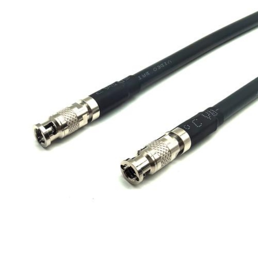
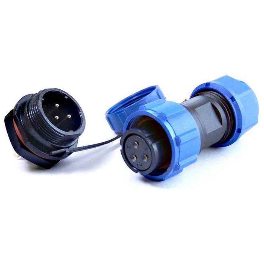
BNC connectors are common in machine vision. Ensure they’re rated for the same impedance as the cable.
- Avoid Adaptors
Impedance-matching adaptors introduce points of failure. Opt for native connections wherever possible.
FAQs About Coaxial Cable Impedance
Q: Can I use a 50 Ω cable in a 75 Ω system?
A: Avoid it. While adaptors exist, mismatched cables risk signal loss and reflections.
Q: Does cable length affect impedance?
A: No—impedance is a material property. However, longer cables increase attenuation, which exacerbates mismatch effects.
Q: How do I test for impedance mismatches?
A: Use a time-domain reflectometer (TDR) or consult the manufacturer’s datasheet.


