What is the inductance of machine cable
In the complex ecosystem of industrial machinery, machine cables serve as the vital lifelines that transmit electrical energy and signals, ensuring the seamless operation of equipment ranging from manufacturing robots to heavy-duty industrial motors. Among the key electrical properties that define the performance of these cables, inductance stands out as a critical factor that directly impacts functionality, efficiency, and even the longevity of connected machinery. For engineers, maintenance professionals, and procurement teams navigating the selection and use of machine cables, a comprehensive understanding of inductance is not just a technical detail—it is a prerequisite for optimizing system performance and avoiding costly operational issues. This article delves into the fundamentals of machine cable inductance, exploring its definition, influencing factors, measurement methods, real-world implications, and practical considerations for industrial applications.
1. The Basic Definition of Machine Cable Inductance
Inductance, in the context of electrical circuits, is the property of a conductor that opposes changes in the electric current flowing through it. When current passes through a machine cable, it generates a magnetic field around the conductor. As the current changes—whether increasing, decreasing, or reversing direction—this magnetic field also changes. According to Faraday’s Law of electromagnetic induction, a changing magnetic field induces an electromotive force (EMF) in the conductor itself (a phenomenon known as self-inductance) and in nearby conductors (mutual inductance). It is this self-inductance that we primarily refer to when discussing the inductance of a machine cable.
Mathematically, inductance (denoted by the symbol “L”) is quantified as the ratio of the magnetic flux linkage (the total magnetic flux passing through all the turns of a conductor, if coiled) to the current generating that flux. The unit of inductance is the henry (H), named after the American scientist Joseph Henry. In practical industrial settings, machine cables typically have inductance values ranging from microhenries (μH, 10⁻⁶ H) to millihenries (mH, 10⁻³ H), as their designs are optimized for low to moderate inductance to minimize energy loss and signal distortion.
Unlike resistance, which dissipates electrical energy as heat, inductance stores energy in the magnetic field and releases it as the current changes. This energy storage and release cycle is what makes inductance both a useful and challenging property: in some cases, it can be harnessed (e.g., in filters to stabilize current), but in machine cables, excessive inductance often leads to inefficiencies and performance issues.
2. Key Factors Influencing the Inductance of Machine Cable
The inductance of a machine cable is not a fixed value; it is shaped by a combination of design, material, and environmental factors. Understanding these variables is essential for selecting cables that align with specific industrial requirements and for troubleshooting inductance-related problems. Below are the most significant factors:
2.1 Cable Length
The length of the machine cable has a direct and linear relationship with its inductance: the longer the cable, the higher the inductance. This is because a longer conductor provides more surface area for the magnetic field to form and interact with the current. For example, a 10-meter machine cable used to power a conveyor belt will have twice the inductance of a 5-meter cable of the same type, assuming all other factors are identical. In industrial facilities where machinery is often spaced apart (e.g., in large manufacturing plants), cable length becomes a critical consideration—extending cables beyond necessary lengths can inadvertently increase inductance, leading to voltage drops and reduced power delivery efficiency.
2.2 Cross-Sectional Area of the Conductor
The cross-sectional area of the cable’s conductor (the part that carries the current, usually made of copper or aluminum) inversely affects inductance: larger cross-sectional areas result in lower inductance. This is because a thicker conductor allows current to distribute more evenly across its surface (reducing the “skin effect,” where high-frequency current tends to flow near the conductor’s surface), which in turn reduces the strength of the magnetic field generated per unit of current. For instance, a machine cable with a 4 mm² conductor will have lower inductance than a 2.5 mm² cable of the same length, making it a better choice for high-current applications like industrial motors, where minimizing inductance is crucial to avoid overheating.
2.3 Magnetic Permeability of the Surrounding Medium
Magnetic permeability (denoted by “μ”) is a measure of how easily a material can be magnetized by an external magnetic field. The medium surrounding the machine cable—whether it is air, plastic insulation, or metal conduit—directly impacts the cable’s inductance. Materials with higher permeability (e.g., iron or steel) amplify the magnetic field around the conductor, increasing inductance. In contrast, non-magnetic materials (e.g., PVC insulation or air) have low permeability, resulting in lower inductance.
This factor is particularly relevant in industrial environments where machine cables are often routed through metal enclosures or alongside steel structures. For example, a cable run through a steel conduit will have higher inductance than the same cable run in open air. Engineers must account for this when designing cable pathways to avoid unintended inductance spikes that could disrupt signal transmission or power delivery.
2.4 Cable Configuration and Spacing
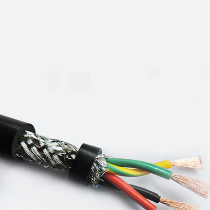
The way machine cables are configured—whether they are single-conductor, twisted-pair, or multi-core—and their spacing from other cables also influence inductance. Twisted-pair cables, for instance, are designed to reduce inductance (and electromagnetic interference, or EMI) by twisting the two conductors together. This twisting causes the magnetic fields generated by each conductor to cancel each other out, lowering the overall self-inductance. This is why twisted-pair machine cables are commonly used in signal transmission applications, such as connecting sensors to control systems, where low inductance is essential for maintaining signal integrity.
Similarly, the spacing between parallel machine cables affects mutual inductance. When two cables carry current in the same direction, their magnetic fields reinforce each other, increasing mutual inductance; when currents flow in opposite directions, the fields cancel out, reducing mutual inductance. In industrial setups where multiple cables are routed alongside each other (e.g., in cable trays), proper spacing and arrangement can help minimize mutual inductance and prevent cross-talk between signals.
3. Measuring the Inductance of Machine Cable: Methods and Considerations
Accurately measuring the inductance of machine cables is critical for quality control during manufacturing, for verifying compliance with industry standards, and for diagnosing performance issues in existing systems. Several reliable methods are used in industrial settings, each with its own advantages and ideal use cases.
3.1 Inductance Meters (L-Meters)
Inductance meters, or L-meters, are the most common tools for measuring cable inductance. These devices work by applying an alternating current (AC) signal of a known frequency to the cable and measuring the resulting voltage and current. Using the relationship between inductive reactance (X_L = 2πfL, where f is the frequency of the AC signal), the meter calculates the inductance (L) by solving for L = X_L / (2πf).
Portable L-meters are widely used for on-site testing, allowing technicians to measure cables already installed in machinery or cable trays. Bench-top L-meters, on the other hand, offer higher precision and are typically used in manufacturing facilities to test cables during production. When using an L-meter, it is important to select a frequency that matches the cable’s intended operating frequency—for example, a machine cable used in a 50 Hz industrial power system should be tested at 50 Hz to get accurate results.
3.2 Impedance Analyzers
For more advanced applications, impedance analyzers are used to measure not just inductance but also other electrical properties like resistance and capacitance. These devices apply a range of AC frequencies to the cable and plot the impedance (the total opposition to current flow, combining resistance, inductive reactance, and capacitive reactance) across the frequency spectrum. By analyzing this impedance curve, engineers can determine the cable’s inductance at different frequencies, which is valuable for cables used in variable-frequency drives (VFDs) or high-frequency signal transmission.
Impedance analyzers are particularly useful for detecting subtle inductance variations caused by manufacturing defects, such as uneven conductor thickness or faulty insulation. This makes them an essential tool for quality assurance in high-precision industries like aerospace or medical device manufacturing, where even small inductance deviations can lead to catastrophic failures.
3.3 Considerations for Accurate Measurement
To ensure accurate inductance measurements, several factors must be taken into account:
- Environmental Conditions: Temperature and humidity can affect the electrical properties of the cable’s insulation and conductor. Measurements should be taken in a controlled environment, or adjustments should be made to account for ambient conditions.
- Cable Termination: Poorly terminated cables (e.g., loose connections or corroded terminals) can introduce additional resistance or capacitance, skewing inductance readings. Cables should be properly terminated before testing.
- External Interference: Magnetic fields from nearby electrical equipment (e.g., motors, transformers) can interfere with measurements. Testing should be conducted away from such sources, or shielding should be used to minimize interference.
4. The Impact of Machine Cable Inductance on Equipment Performance
The inductance of machine cables is not a theoretical concept—it has tangible effects on the performance, efficiency, and reliability of industrial equipment. Ignoring inductance can lead to a range of issues, from minor inefficiencies to severe equipment damage. Below are the key impacts to consider:
4.1 Voltage Drops and Power Loss
When current flows through a machine cable, the inductive reactance (X_L) opposes the current, leading to a voltage drop across the cable. This voltage drop is calculated using Ohm’s Law for AC circuits: V = I × X_L, where I is the current. In high-current applications (e.g., industrial motors or heavy machinery), even a small inductance can result in significant voltage drops, reducing the voltage available to the connected equipment.
For example, a machine cable with an inductance of 10 μH carrying a 50 A current at 50 Hz has an inductive reactance of X_L = 2π × 50 × 10×10⁻⁶ = 0.00314 Ω. The voltage drop across the cable is then V = 50 × 0.00314 = 0.157 V. While this may seem small, in a system where the equipment requires a precise voltage (e.g., a 480 V motor), multiple such voltage drops across long cable runs can add up, causing the motor to operate at a lower voltage than intended. This reduces the motor’s torque and efficiency, leading to slower operation and increased energy consumption.
4.2 Electromagnetic Interference (EMI)
The magnetic field generated by a current-carrying machine cable can interfere with nearby electronic devices, such as sensors, control systems, or communication cables. This interference, known as EMI, can distort signals, leading to incorrect readings, erratic equipment behavior, or even system failures.
For example, in an automated manufacturing line, a machine cable with high inductance powering a robotic arm can generate a strong magnetic field that interferes with a nearby proximity sensor. This interference could cause the sensor to fail to detect the presence of a workpiece, leading the robot to make incorrect movements and potentially damaging the workpiece or the robot itself. Twisted-pair cables and shielded cables are often used to mitigate this issue, but selecting a cable with the right inductance in the first place is a more effective long-term solution.
4.3 Overheating and Equipment Damage
Excessive inductance can also lead to overheating in machine cables and connected equipment. When current changes rapidly (e.g., in VFD systems or equipment with frequent start-stop cycles), the induced EMF from the cable’s inductance can cause current spikes. These spikes increase the power dissipation in the cable (P = I²R, where R is the cable’s resistance), leading to overheating.
Over time, overheating can degrade the cable’s insulation, increasing the risk of short circuits. In extreme cases, short circuits can cause electrical fires or damage to expensive equipment like motors or control panels. For example, a machine cable with degraded insulation due to inductance-related overheating might short-circuit, causing a motor to burn out—a repair that could cost thousands of dollars and result in extended downtime for the facility.
5. Practical Considerations for Selecting Machine Cables Based on Inductance
Given the significant impact of inductance on equipment performance, selecting the right machine cable requires careful consideration of inductance alongside other factors like current capacity, voltage rating, and environmental resistance. Below are practical guidelines to help with the selection process:
5.1 Match Cable Inductance to Operating Frequency
The inductive reactance of a cable increases with frequency (X_L = 2πfL), meaning that cables used in high-frequency applications (e.g., VFDs, which operate at frequencies up to 1000 Hz) are more sensitive to inductance. For these applications, low-inductance cables—such as those with larger conductors, twisted-pair configurations, or low-permeability insulation—should be selected to minimize voltage drops and EMI.
In contrast, cables used in low-frequency applications (e.g., 50/60 Hz power distribution) are less affected by inductance, and other factors like current capacity may take priority. However, even in low-frequency systems, long cable runs can increase inductance to problematic levels, so cable length should still be considered.
5.2 Prioritize Conductor Material and Size
Copper conductors have lower resistance than aluminum conductors, which helps reduce power loss and, indirectly, inductance-related issues. For applications where inductance is a concern, copper conductors are preferred. Additionally, selecting a cable with a larger cross-sectional area reduces inductance (as discussed earlier) and increases current-carrying capacity, making it ideal for high-current equipment.
For example, a 6 mm² copper cable will have lower inductance and higher current capacity than a 4 mm² aluminum cable, making it a better choice for powering a 10 HP industrial motor.
5.3 Consider Cable Shielding and Configuration
Shielded machine cables are designed to reduce EMI by containing the magnetic field generated by the conductor. For applications where EMI is a critical concern (e.g., sensor cables or communication cables), shielded cables should be selected. Twisted-pair configurations, as mentioned earlier, also reduce inductance and EMI by canceling out magnetic fields, making them suitable for signal transmission.
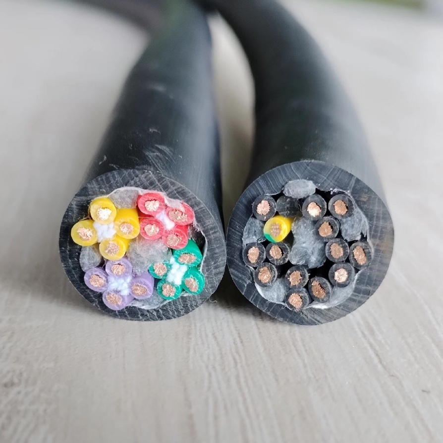
In multi-core cables (cables with multiple conductors), the arrangement of the cores can impact inductance. Cores that are twisted together or arranged symmetrically have lower mutual inductance, reducing cross-talk between conductors.
6. Why FRS Brand Factory Is Your Trusted Partner for High-Quality Machine Cables
When it comes to machine cables that deliver consistent inductance performance, reliability, and durability, FRS Brand Factory stands out as a leading manufacturer in the industrial sector. For over a decade, FRS has been dedicated to producing machine cables that meet the strictest industry standards and address the unique inductance-related needs of industrial applications. Here’s why FRS should be your first choice for machine cables:
6.1 Precision Engineering for Optimal Inductance
At FRS, we understand that inductance is not a one-size-fits-all property—different industrial applications require cables with specific inductance values to ensure optimal performance. Our team of electrical engineers uses advanced design software and rigorous testing to develop machine cables with precisely controlled inductance. We carefully select conductor materials (high-purity copper for low resistance and inductance), optimize cross-sectional areas, and choose low-permeability insulation materials to minimize inductance where needed. For high-frequency applications like VFDs, our twisted-pair and shielded cables are engineered to reduce inductance and EMI, ensuring stable power delivery and signal integrity.
Every FRS machine cable undergoes thorough inductance testing using state-of-the-art impedance analyzers and L-meters, ensuring that each product meets the exact inductance specifications outlined by our customers. Whether you need a cable with a low inductance of 5 μH for a sensor system or a moderate inductance of 50 μH for a motor application, FRS delivers consistent, reliable performance.
6.2 Durability and Adaptability to Industrial Environments
Industrial environments are harsh—machine cables are exposed to extreme temperatures, moisture, chemicals, and physical abrasion. FRS machine cables are built to withstand these conditions without compromising inductance performance. Our cables feature rugged insulation materials (such as PVC, XLPE, and PTFE) that resist temperature fluctuations (-40°C to 125°C) and chemical corrosion, ensuring that the inductance remains stable even in the most demanding settings. Additionally, our cables are designed with flexible conductors to withstand repeated bending and movement, making them ideal for robotic arms and other moving machinery.
We also offer customizable cable solutions to meet unique industrial needs. Whether you require a cable of a specific length, a specialized shielding configuration, or a conductor size tailored to your current requirements, our team works closely with you to design a cable that aligns with your inductance and performance goals.
6.3 Compliance with Global Standards and Quality Assurance
FRS Brand Factory is committed to delivering machine cables that meet or exceed global industry standards, including IEC, UL, and CSA. Our manufacturing facilities are ISO 9001 certified, ensuring that every step of the production process—from material sourcing to final testing—is subject to strict quality control. We source only high-quality raw materials from trusted suppliers, and each batch of cables undergoes multiple quality checks, including inductance testing, resistance testing, and insulation resistance testing, to ensure durability and performance.
Our dedication to quality has made FRS a trusted partner for businesses across industries, including manufacturing, automotive, aerospace, and renewable energy. Customers rely on FRS machine cables to power their critical equipment, knowing that our products will maintain stable inductance, minimize power loss, and reduce the risk of EMI-related issues.
6.4 Exceptional Customer Support and Technical Expertise
At FRS, we believe that customer support extends beyond delivering a quality product. Our team of technical experts is available to provide guidance on selecting the right machine cable for your application, based on factors like inductance, current capacity, and environmental conditions. We also offer on-site support for cable installation and testing, ensuring that your system operates at peak efficiency.
Whether you are a small manufacturing facility or a large industrial enterprise, FRS Brand Factory is committed to providing you with machine cables that meet your performance needs and exceed your expectations. With our focus on precision, durability, and customer satisfaction, we are your trusted partner for all your machine cable requirements.


